Neon Blubs Show Microwave Distribution in Oven Videos for Engineers
Here
is a really cool demonstration showing the distribution of microwaves inside a kitchen microwave oven.
Experimenter Zeke Kossover drilled an array of holes in an acrylic panel, into which he inserted neon bulbs. Per
Zeke, "Microwaves are invisible, so you can't see them inside microwave oven, but their presence can be detected
with neon lamps. The changing electromagnetic field from the microwaves will make charged particles move, and so
the electrons in the metal legs will move creating current. This current makes the lamps glow." You can see how
the field changes as the panel rotates, and also how the presence of a substance that absorbs the energy affects
the pattern.
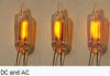
A
typical
NE-2 type neon bulb, likely used in the experiment, turns on at about 65 VAC or 90 VDC. Once the bulb starts
conducting, the resistance goes down and the voltage drop across the bulb lowers by about 10 volts. The nearly
constant voltage made neon bulbs useful as voltage regulators before semiconductor devices like Zener diodes
became available. Since the trigger voltage is what determines when the neon begins to conduct, that explains why
65 VAC, with a peak of 65 Vrms x √2 = 92 Vpk, turns it on while 90 volts of direct current must be applied. All
that need to be done to turn the bulbs on is to immerse them an electric field with an orientation sufficient to
induce the trigger voltage.
This archive links to the many video and audio
files that have been featured on RF Cafe.
RF Cafe began life in 1996 as "RF Tools"
in an AOL screen name web space totaling 2 MB. Its primary purpose was to provide
me with ready access to commonly needed formulas and reference material while performing
my work as an RF system and circuit design engineer. The World Wide Web (Internet)
was largely an unknown entity at the time and bandwidth was a scarce commodity.
Dial-up modems blazed along at 14.4 kbps while tying up your telephone line,
and a lady's voice announced "You've Got Mail" when a new message arrived...

 Here
is a really cool demonstration showing the distribution of microwaves inside a kitchen microwave oven.
Experimenter Zeke Kossover drilled an array of holes in an acrylic panel, into which he inserted neon bulbs. Per
Zeke, "Microwaves are invisible, so you can't see them inside microwave oven, but their presence can be detected
with neon lamps. The changing electromagnetic field from the microwaves will make charged particles move, and so
the electrons in the metal legs will move creating current. This current makes the lamps glow." You can see how
the field changes as the panel rotates, and also how the presence of a substance that absorbs the energy affects
the pattern.
Here
is a really cool demonstration showing the distribution of microwaves inside a kitchen microwave oven.
Experimenter Zeke Kossover drilled an array of holes in an acrylic panel, into which he inserted neon bulbs. Per
Zeke, "Microwaves are invisible, so you can't see them inside microwave oven, but their presence can be detected
with neon lamps. The changing electromagnetic field from the microwaves will make charged particles move, and so
the electrons in the metal legs will move creating current. This current makes the lamps glow." You can see how
the field changes as the panel rotates, and also how the presence of a substance that absorbs the energy affects
the pattern.
 This archive links to the many video and audio
files that have been featured on RF Cafe.
This archive links to the many video and audio
files that have been featured on RF Cafe.


