 All RF Cafe Quizzes make great fodder for
employment interviews for technicians or engineers - particularly those who are
fresh out of school or are relatively new to the work world. Come to think of it,
they would make equally excellent study material for the same persons who are going
to be interviewed for a job. Bonne chance, Viel Glück, がんばろう,
buena suerte, удачи, in bocca al lupo, 행운을 빕니다,
ádh mór, בהצלחה, lykke til, 祝你好運.
Well, you know what I mean: Good luck! All RF Cafe Quizzes make great fodder for
employment interviews for technicians or engineers - particularly those who are
fresh out of school or are relatively new to the work world. Come to think of it,
they would make equally excellent study material for the same persons who are going
to be interviewed for a job. Bonne chance, Viel Glück, がんばろう,
buena suerte, удачи, in bocca al lupo, 행운을 빕니다,
ádh mór, בהצלחה, lykke til, 祝你好運.
Well, you know what I mean: Good luck!
Click here for the complete list of
RF Cafe Quizzes.
Note: Some material based on books have quoted passages.
Return to RF Cafe Quiz #14
1. Who from this list is usually credited with being the first to experiment with high frequency
oscillator circuits? b) Nikola Tesla Nikola Tesla's work with high frequency oscillators predated
those of Marconi (whose name is not in the list of options to avoid contention). An extensive archive of Tesla's
achievements can be found at the Tesla Society website.
2. In the four basic oscillator circuits shown below, what is the primary function of the transistor? c)
Compensations for tank circuit losses A parallel tank circuit composed of an ideal (lossless, i.e., purely
reactive) inductor and and ideal capacitors will theoretically "ring" (oscillate) in perpetuity at its resonant
frequency once stimulated. Since real-world components have losses (resistance), the oscillations eventually
dampen out to an unusable amplitude. Although the transistor can and usually does provide signal gain to the load,
its primary purpose is to feed enough energy back into the tank circuit to sustain oscillations.
 3.
Which type of oscillator circuit is shown to the right? 3.
Which type of oscillator circuit is shown to the right? b) Clapp oscillator The Clapp oscillator,
invented by James K. Clapp
(page 5), is an improvement over the basic Colpitts oscillator due to the addition of a capacitor in series
with the parallel inductor.
 4.
Which type of oscillator circuit is shown to the right? 4.
Which type of oscillator circuit is shown to the right? c) Hartley oscillator The Hartley oscillator,
invented by Ralph
V. L. Hartley, uses a tank circuit composed fundamentally of a pair of inductors (or a tapped transformer) in
parallel with a capacitor. The tap point between the inductors is a reactive voltage divider to provide feedback
to the transistor.
 5.
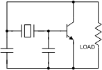
Which type of oscillator circuit is shown to the right? 5.
Which type of oscillator circuit is shown to the right? d) Pierce oscillator The Pierce oscillator,
invented by George
W. Pierce, replaces the LC tank circuit with a crystal as the frequency determining element. Capacitors are
used to stabilize the circuit.
 6.
Which type of oscillator circuit is shown to the right? 6.
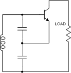
Which type of oscillator circuit is shown to the right? a) Colpitts oscillator The Colpitts
oscillator, invented by Edwin H. Colpitts,
uses a tank circuit composed fundamentally of a pair of capacitors in parallel with an inductor. The tap point
between the capacitors is a reactive voltage divider to provide feedback to the transistor.
7. Which factor is most important in maintaining spectral purity in an oscillator circuit? a) Overall
circuit Q If all of the circuit components have extremely high Qs but the layout and/or shielding is poor,
then the overall Q will be diminished. Similarly, a clean layout with poor component Qs will result in suboptimal
performance.
8. What does the term "frequency pulling" refer to? b) Change in frequency due to load
variations Although the other two factors, temperature and power supply variations for the load can cause its
impedance to change and pull the oscillator frequency, they are lumped into the load variations definition, so b)
is the most accurate choice. 1/2 credit goes for an answer of d). 9. In a phase-locked loop (PLL)
oscillator circuit, what does the phase detector do? b) Compares relative phase between the reference
input and oscillator output and introduces a shift as necessary to maintain phase coherence 10.
Complete the following adage used in the days before computer simulators. "If you want an oscillator, design an
amplifier. If you want an amplifier, design a(n) ____." c) Oscillator In the days of yore, when
dinosaurs roamed the Earth, it was nearly impossible to design high frequency circuits that behaved as intended on
the first pass. The relatively large size of components made isolating circuit inputs from circuit outputs very
difficult, and often times stray energy from the output of an amplifier circuit would feed back to the input at
just the right phase to induce oscillations. Tweaking of component values and physical locations would be needed
to tame the beast. Similarly, attempts to lay out oscillator circuits to intentionally get just the right feedback
in phase and amplitude for sustaining oscillation would fall short of expectation, again necessitating tweaking.
Use of modern circuit and EM simulators has removed a lot of the unknowns, permitting high confidence in getting
it right the first time. |


 3.
Which type of oscillator circuit is shown to the right?
 4.
Which type of oscillator circuit is shown to the right?
 5.
Which type of oscillator circuit is shown to the right?
 6.
Which type of oscillator circuit is shown to the right?