Servo Side

Motor Side

Crystal Side

PCBs Plugged Together

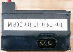
Case Sections
See my other Blade CP page, with in-flight videos, on my
AirplanesAndRockets.com
website.
E-flite's Blade CP radio controlled electric helicopter comes from the factory
with a 4-in-1 electronics unit that contains a 6-channel receiver that performs
the functions needed for motor control, piezoelectric gyroscope, BEC (battery eliminator
circuit), and ESC (electronics speed control). It also includes a dual-gimbal transmitter
with an idle-up switch for transitioning to aerobatic mode where both positive and
negative pitch can be commanded to the rotor head.
My Blade CP has always flown well, but from the very beginning it has been prone
to sudden, uncommanded control movements (glitches). The results have varied from
slight jerkiness in the flight to a sudden high speed climb-outs (really bad when
inside).
Online forums have reported the problem, but most attribute the behavior to a
"sticky" swash plate. I know without a doubt that my swash plate is very free-moving.
I have tried running the helicopter at near full rotor speed and watching for electronic
glitches in the controls, but so far have not seen any. The heli has not had any
really hard landings, but I did notice that the double-sided tape securing the 4-in-1
to the vertical mounting surface on the main frame had come loose. Replacing it
cured much of the jerkiness, but some remains. Just for the heck of it, I decided
to open the 4-in-1 and take a look inside for cracked solder joints or damaged components.
I did not find any. So, everything was put back together and re-installed in the
helicopter. As of this writing, it has not been flown so I cannot report whether
the problem is still there, better, or worse.
While the 4-in-1 was apart, I decided to photograph it and try to identify some
of the components. There are two, double-sided PCBs that plug into each other via
a 6-pin header. The photo to the left shows the two PCBs removed from the
case, but plugged together as they would be in the case. Partitioning of the circuitry
appears to have all the RF circuitry on one PCB and the digital processor and high
current drivers on the other - good system design to be sure. Four screws hold the
case lids on the top and the bottom, with a central case section holding the two
PCBs in position, and providing a physical barrier between them. The antenna is
captured in a groove between the case sections.

Crystal + Filters Radio PCB

Controller + Drivers Controller PCB

Receiver + Demodulator Radio PCB

Gyro + ESC Controller PCB
One PCB contains the radio circuitry that performs receiver and demodulation
functions. On one side (photo to the left) it has two tunable transformers where
the antenna enters the circuit - most likely one for the tuning the input and the
other for tuning the oscillator. The crystal plugs into the socket between the transformer
and the 455 kHz filter. A large (220 uF) capacitor mounts next to the pin header
row (where servos plug in). A TI LM393 dual differential comparator sits to the
right of the lower transformer. An AHC164 parallel 8-bit serial-in-parallel-out
shift register sits below the big capacitor. The reverse side (photo to the right)
contains the receiver front-end IC (Toshiba
TA31136F
FM detector) and a voltage regulator.
The other PCB performs the ESC, BEC and gyroscope functions. The photo to the
left shows three International Rectifier
7451H power MOSFET drivers
(SOT8 packages) - two in parallel for the main rotor motor and one for the
tail rotor motor - and a muRata GYROSTAR™ JPN
ENC-03M Piezoelectric Vibrating Gyroscope (metal case in left
photo). An LM324 quad opamp is located below the gyro package in the photo. The
reverse side (photo to the right) has an Elan EM78P458AM microcontroller for the
4-in-1, two potentiometers, a clock crystal to the microcontroller, a dual LED for
the red/green indicator, and two CX1117-5.0 voltage regulators (mounted side-by-side
near bottom edge where battery wires enter PCB).
Thanks to Geoff Schulz for correcting the gyro P/N and pointing out that the
cyclic mixing is performed in the transmitter, not the receiver. Geoff has also
extensively studied the mechanism that causes the collective pitch to change with
rapid yaw inputs and has discovered a design/control system flaw that he has submitted
to Horizon Hobby to assist them in correcting the problem. Maybe once the issue
is resolved, he will allow his works to be published here.
Thanks to Eric Jorgensen for pointing out that two of the three FETs are in parallel
for driving the main rotor motor, and the third drives the tail rotor motor.
Posted May 4, 2020
|


