|
|||||||||||||
 |
|||||||||||||
Doherty Amplifiers in UHF |
|||||||||||||
|
White Paper: Doherty Amplifiers in UHF By Walter Sneijers, RF Application Engineer, Ampleon 1. Introduction The triple demands of high efficiency, small size and low cost placed by cellular telephony on UHF transmitters led to the early introduction of Doherty amplifiers in mobile handsets. Since this introduction Doherty architectures have been further enhanced, leading to a gradual uptake of this technology in broadcasting, to the point where Doherty amplifiers are found in almost all of today's new UHF transmitters.
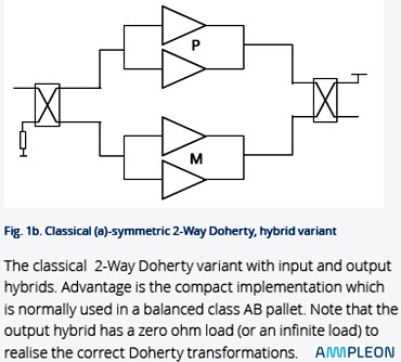
(Note that the use of GaN transistors is not in scope for this article.) 2. Doherty Architectures In the following sections two common Doherty architectures are reviewed, the classical 2-way and the ultra wide-band, (UWB) architectures. 2.1 Classical 2-Way Doherty Architecture Fig 1a shows a classical Doherty power amplifier architecture which actually consists of two amplifiers: one operating as a main, or "carrier," amplifier biased as Class AB, the other as a "peaking" amplifier biased for Class C operation to provide a high-efficiency power boost when needed for higher-power input excursions. The input signal is evenly split using a 3-dB quadrature coupler. The two outputs from the coupler are 90⁰ out of phase and are brought back into phase and reactively combined using the quarter-wave transmission line of the peaking amplifier. The two signals in parallel create an impedance of Z0/2 Ω which is stepped up to Z0 Ω by the quarter-wave transformer. An amplifier based on the classic Doherty architecture only operates over a 50 MHz bandwidth range and has somewhat limited power levels, but it does provide high efficiency for signals with high peak/average ratios.
The a-symmetric Doherty architecture, shown in fig 1b, gives a 2-3% increase in average efficiency compared to the above classic 2-way design and this architecture also offers increased power levels. This design uses the same main amplifier but with a higher power peak amplifier and can be implemented, for example, using Ampleon's BLF888B, (Main) and BLF898, (Peak). In this case the BLF898 peak amplifier, with around 900 W, has around 1.5 times the power of the BLF888B main amplifier, with 650 W, giving an α = 0.4, (where α is the ratio of the main amplifier power over the sum of the main and peak amplifier powers). Figures 2a and 2b show how higher amplifier efficiencies can be obtained by varying the power of the peak amplifier. Note however that this design is more complex than the classic 2-way and the relatively small increase in power and efficiency may or may not justify this extra complexity.
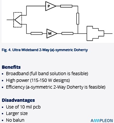
2.2 Ultra Wideband 2-Way Doherty Architecture
A theoretical UWD design enables coverage of the full UHF spectrum, albeit at a reduced efficiency level, as shown in figure 3a. However practical considerations such as parasitics in the output stages and 2nd order harmonics limit the achievable bandwidth. An implementation of this design is possible using the Ampleon BLF888D transistor which enables full coverage of the UHF band at 40% efficiency with an output power of 115 W avg. However the efficiency of this implementation is limited by the nature of the output circuitry and also 2nd order harmonics introduced by channel filters. These and other factors are difficult to mitigate and can significantly lower efficiency, by as much as 5%. Given these limitations it is important to be able to combine UWB Doherty amplifiers in order to achieve full UHF bandwidth coverage at acceptable efficiency levels and this is discussed in more detail below.
If however the UHF spectrum is split into three sub-bands, e.g. 470-600 MHz, 600-700 MHz and 700-800 MHz then higher efficiency levels are achievable since Doherty designs are less susceptible to 2nd order harmonics and output matching can be improved when the covered spectrum is lower. As an example of what can be achieved by this approach, Ampleon have produced a development board, based on the BLF888D transistor, which enables 45% efficiency at an average power of 130 Watts over the 470-600 MHz sub-band. The above discussion has illustrated the trade-off between efficiency and bandwidth when using current UWD technologies. This choice will be influenced in different regions by factors such as transmitter requirements, (size, cost and power consumption) and end-user requirements - again predominantly cost and size. The evolving regulatory landscape may also influence design changes as regional authorities review future use of UHF spectrum. 2.2.2 Combining of UWD Amplifiers Where power and efficiency requirements dictate that the UHF spectrum must be split into sub-bands then amplifier outputs must be combined. Three main combining techniques are commonly used in UHF solutions - Wilkinson Combiners, Baluns and 90° couplers, each with their respective pros and cons. In this section we focus on the 90° coupler and the Balun and examine their performance when isolating 2nd order harmonics - a key characteristic of any coupling device. Balun: An ideal balun provides:
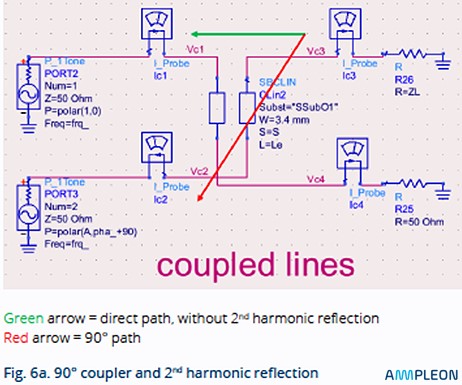
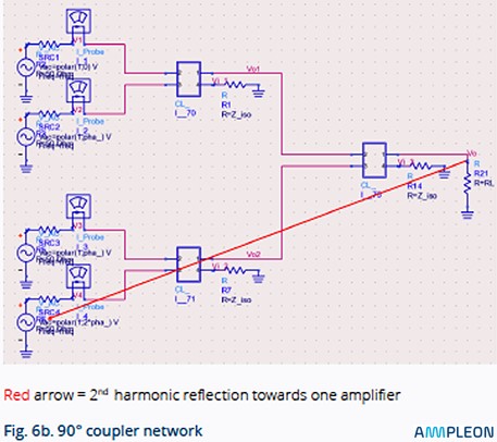
Although this precludes the use of baluns from any Doherty designs covering the full UHF band, they can be used in solutions where the UHF band is divided into sub-bands, as shown in figure 5c, where 120 MHz bandwidth is achievable. 90° Coupler: Nowadays, in most cases the combiner used with UWD amplifiers is a 90° coupler, a four-port device used either to equally split an input signal with a resultant 90° phase shift between output ports or to combine two signals while maintaining high isolation between the ports. This configuration ensures a high degree of isolation between the two output ports and the two input ports without unwanted interaction between them. The characteristics of the coupler are such that the direct, or 0 path isolates 2nd harmonic reflections and the 90° path passes on 2nd harmonic reflections. This means that only one amplifier will see a harmonic reflection - see fig 6a. When more 90° couplers are used (see Fig. 6b: three couplers used) only one transistor out of four will see a full reflection.
© Ampleon Netherlands B.V. 2016 All rights reserved. Reproduction in whole or in part is prohibited without the prior written consent of the copyright owner. The information presented in this document does not form part of any quotation or contract, is believed to be accurate and reliable and may be changed without notice. No liability will be accepted by the publisher for any consequence of its use. Publication thereof does not convey nor imply any license under patent- or other industrial or intellectual property rights.
Posted June 1, 2018 |
|||||||||||||
 |
|||||||||||||
|
|||||||||||||


|
||||||||||||||||||||||||||||||||||||


