|
Try finding the equation for phase angle error due to VSWR mismatch, and you
will likely fail. Extensive keyword searches for related terms will turn up websites
that present the formula for amplitude error due to VSWR mismatch, but not for phase
angle error due to VSWR mismatch. If you are fortunate enough to find the equation,
you almost certainly will not be given the derivation.
The actual equation, εθmax = |Γ1 | • |Γ2|, is so simple that it seems unbelievable,
but here its validity is demonstrated.
Well, the search is over thanks to Haris Tabakovic, who was kind enough to provide
this excellent derivation for the benefit of RF Cafe visitors.

V1 = Vi • T1
V2 = Vi • T1 • e-jβl
Vo = Vi • T1 • T2• e-jβl
Vo is expected output signal.
At the same time, the reflected signal is being bounced around on the connecting
transmission line. First order reflections are going to be dominant, and higher
order reflections are not taken into account. Note that the transmission line is
assumed to be lossless.
Then we can express reflected signal at V2 as:
V2r = Vi • T1 • e-jβl
• Γ2
This signal travels back and reflects again at V1 :
V1r = V2r • e-jβl • Γ1
= Vi • T1 • e-jβl • Γ2 • e-jβl
• Γ1
Finally, this error signal Voe is transmitted and superimposed on
expected output signal, causing phase and amplitude error:
Voe = V1r • e-jβl • T2
= Vi • T1• e-jβl • Γ2 • e-jβl
• Γ1 • e-jβl • T2
Voe = Vi • T1 • T2•
Γ1 • Γ2 • e-j3βl
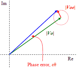
We can represent these signals in complex plane as:
|
|Vo| = |Vi| • |T1| • |T2|
|Voe| = |Vi| • |T1| • |T2| • |Γ1| • |Γ2|
|
 |
It follows that we can write the worst-case phase error εθmax as:

Since εθmax will be a very small angle, can say that:
tg(εθmax) ≈ εθmax
Finally, we can write the worst-case phase error (in radians) due to reflections
at the source and at the load as:
εθmax = |Γ1| • |Γ2|
Here is an online VSWR mismatch calculator.
Posted June 6, 2023
(updated from original post
on 2/15/2009)
|


