|
February 28, 1964 Electronics
 [Table of Contents] [Table of Contents]
Wax nostalgic about and learn from the history of early electronics.
See articles from Electronics,
published 1930 - 1988. All copyrights hereby acknowledged.
|
A well-laid-out and routed
chassis, control panel, equipment rack, or circuit breaker panel has always invoked
the same sort of appreciation and awe in me that a Rembrandt painting invokes in
an art cognoscente or a Beethoven concert invokes in a music aficionado. Many moons
ago when I worked as an electrician, I prided myself in obsessively neat and orderly
runs of conduit and Romex™ cable (with no twists), squarely mounted receptacle and
switch boxes, and rigid compliance with NEC requirements. Once I entered into the
RF and microwave realm, an entirely new kind of eye candy appeared in the form of
semi-rigid coaxial cable and waveguide runs. Knowing the technical (electrical)
requirements and limitations based on power, wavelength, and VSWR concerns served
to enhance the appreciation. Electrical wiring has its own unique requirements for
bend radii, enclosure fill, and voltage levels, due to heating, mechanical stress,
and voltage induction issues. RF transmission media adds to that signal reflections
due to contamination and cross-section perturbations, dissimilar junction spurious
mixing products, microphonics, common mode currents, and a host of other idiosyncrasies.
The photos in this article, of course, caught my eye and had to be reproduced for
like-minded people.
Production Techniques - Fixtures Form Semirigid Coax
Close tolerances and tight specs maintain electrical characteristics

Shields are soldered to interconnect bracket, and inner conductors
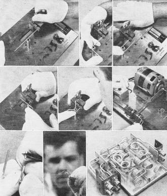
are soldered inside the bracket, in this phase comparator assembly

Forming method employed with adjustable fixture is shown by first
five photos (see text for details). Shield is trimmed and removed. Parts are then
assembled.
Deer Park, N. Y. - Production employees used to working with conventional wire
and cable can readily switch to fabricating assemblies of the relatively new semirigid
coaxial cable - if suitable forming fixtures are used and if cable specifications
are chosen to avoid production problems.
Methods must be worked out carefully because even seemingly insignificant liberties
in manufacturing and design can introduce marked changes in VSWR, impedance match
and other electrical characteristics, according to manufacturing engineers at Airborne
Instruments Laboratory, a division of Cutler-Hammer.
AIL uses semirigid coaxial cable for crossover hybrids, phase comparators and
similar devices because of its excellent shielding qualities and the ease with which
precise electrical length can be obtained. In assembly fabrication, mechanical length
tolerances of ±0.005 inch are standard and ±0.002 inch can be held.
Bend radii of 5/16th inch are repeatedly achieved, without damage to the cable or
change in electrical characteristics.
Forming the Cable - To form the cable, AIL developed fixtures
designed to eliminate as much as possible the kinks, score marks, burrs and other
defects that would change the electrical characteristics.
When a large run of similar parts is required, a special-purpose fixture is generally
best. For short runs, AIL uses adjustable fixtures like the one shown in the series
of photographs. This fixture has removable bending mandrels, a vernier scale for
positioning the cable, and a holding device.
Operations illustrated include: (1) clamping the cable in the fixture; (2) bending
the cable 90 degrees around the post; (3) repositioning the cable and bending again
to form a U; (4) making another 90-deg bend; (5) shifting the post to another position
so the cable end will swing over the top of the fixture.
Trimming the Shield - In the next photo, the metal shield is
cut by a motorized trimmer. The machine is set to cut only the shield, to an accuracy
of 0.0001 inch. The cut end of the shield is removed with pliers, leaving the Teflon
dielectric to protect the inner conductor.
The original blank measured 4.700 ±0.002 inches; 0.750 ±0.001 inch
was trimmed from each end; the finished part meas-ures 3.200 ±0.004 inches.
Parts such as this are used to assemble intricate devices, such as the phase comparator
seen in the last photo.
Soldering Interconnections - Precisely dimensioned interconnect
brackets make assembly easier and prevent impedance mismatches and excessive vswr.
The cut ends of the shielding are soldered to the outside of the bracket, in the
assembly shown, while the inner conductors are soldered together inside the bracket.
One of the soldering problems is that the heat of soldering causes the Teflon
to extrude from the joint. Trimming the Teflon back to the joint allows the remaining
Teflon to spring back inside the outer shield. In both cases, electrical characteristics
are changed. This must be accounted for in the design.
Some manufacturing problems can be solved by careful attention to cable procurement.
Sliding or relative motion between the center conductor and outer shield (caused
by Teflon's low friction) was eliminated by compressing the dielectric within the
shield. Wrinkling and cracking of the shield during bending was avoided by specifying
a minimum elongation.
Posted August 24, 2023
(updated from original
post on 8/27/2018)
|


