|
|||||||||||||
 |
|||||||||||||
Active Filters
|
|||||||||||||
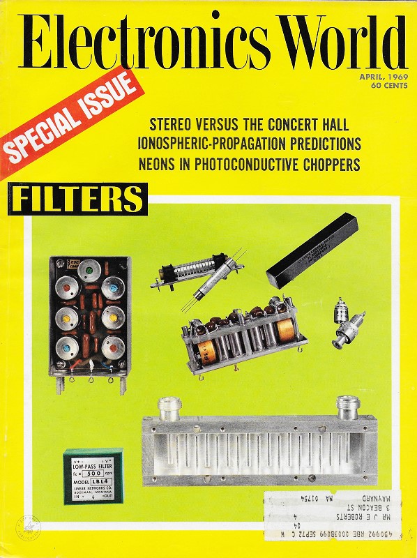
When I first began designing circuits in the 1990s using active filters, the upper frequency was limited to a few tens of kHz because of the gain-bandwidth product of the available amplifiers. That made them useful in baseband circuits, but that was about it. There were also issues with the noise figure and intercept points and intermodulation product levels. Today, you can get fully integrated and programmable active filters which operate at tens of MHz and beyond, and with much better RF-type specifications. That makes them useful in low intermediate frequency (IF) circuits as well as at baseband. BTW, this article is one of about ten dealing with filter types in the April 1969 issue of Electronics World magazine. Active Filters
The author received his BSEE from San Jose College in 1957, his MS from Stanford in 1959, and his PhD from Montana State in 1966. He was formerly associated with Farinon Electric and Douglas Aircraft where he conducted research in the areas of network analysis and synthesis. He presently teaches part-time in the Electrical Engineering Department of Montana State University and has been president of Linear Networks since founding it in 1963. By James L. Hogin / President, Linear Networks Company Filters of this type are able to duplicate frequency responses of passive LC networks. But, as an added bonus, they provide gain. Active filters differ from passive filters in that their operation depends, just as a transistor or any other active device, on an external power source. The most common type of active filter, and the one to be considered here, is the active RC network made up of resistors, capacitors, and active devices. The principal advantage of this filter is that it duplicates the frequency characteristics of an LC filter without the use of inductors. And, in reality, a special external power source is usually not required since the filter is often a part of a system for which power is already supplied. An additional advantage is that the active filter provides signal power gain which a passive filter, by its very nature, is incapable of giving. Although active filters perform satisfactorily at the higher frequencies, they find their greatest use at very low frequencies; frequencies so low that inductive devices are either prohibitively large or are so lossy that they have no practical value. Some areas in which low-frequency active filters are used include medical technology, oceanography, seismology, and others where low-frequency phenomena, such as the beat of a heart or a movement of the earth, are encountered. Operation and Characteristics
Fig. 1 - In the negative-impedance converter, the input impedance, Zin, is the negative of load impedance, ZL. In this case, V1 equals V2. and i1 is same as i2. In active resistance-capacitance networks, the signal to be filtered is applied to the input terminals and the resultant filtered signal extracted from the output terminals. Internally the active filter is considered made up of two portions: an active portion composed of active devices and their associated passive components such as biasing resistors, coupling capacitors, etc., and a passive portion consisting of precision resistors and capacitors which determine the frequency characteristics of the filter. Various active device configurations are used as the active portion of the filter. A sampling of the many types is given in the following paragraphs. 1. The negative-impedance converter, Fig. 1, (commonly known as the NIC) is a device configuration which, when loaded with an impedance at its output terminals, produces the negative of this impedance at its input terminals. Although the NIC has probably received the greatest amount of theoretical attention, it is considered by many to have little practical value. There are two basic types of negative-impedance converters, the current conversion (INIC) type shown in Fig. 1 is where V2 = V1 and i2 = ki1 (k = I in example), and the voltage conversion (VNIC) type is where V1 = -kV2 and i1 = -i2. For either type the input impedance Zin is the negative of the load impedance ZL. The circuit in Fig. 1 can be analyzed as follows. The base-emitter voltage drop of Q1 as well as the voltage drop of the forward-biased diode is small, thus the condition that V2 = V1 is met. When no signal is applied, all resistor currents are equal by symmetry. The input current i1 splits into V1/R1 down through the lower left resistor, [i1 - (V1/R1)] flows through the emitter of Q1. Since the collector and emitter currents of a transistor are approximately the same, the current [i1 - (V1/R1)] flows through the upper left resistor; the voltage across the collector resistor of Q1 is then (R1i1 - V1), positive at the bottom, which is also the voltage across the emitter resistor of Q2 since the base-emitter drop of Q2 is small. The upward emitter, and hence collector, current of Q2 is then [i1 (R1/R2) - (V1/R2)]. But the voltage V2 = V1 causes current V1/R2 to flow in a downward direction in the lower right resistor. Hence, i2 = [(V1/R2) + i1 (R1/R2) - (V1/R2)] = i1 (R1/R2). If R1 is chosen equal to R2, then the condition that i2 = i1 is also fulfilled. The diodes are for base-emitter voltage drop compensation.
Fig. 2 - A gyrator consists of two voltage-to-current converters whose output current is proportional to its input voltage. 2. The gyrator is an active device configuration which produces an output current proportional to its input voltage. In addition, an input current, which is proportional to the output voltage of the device, flows. In other words, the gyrator possesses a significant reverse transconductance as well as a forward transconductance. Essentially, the gyrator circuit consists of two voltage-to-current converters (Fig. 2.). 3. The operational amplifier, in addition to its role as a building block in constructing other active device configurations, is useful when connected in the standard inverting or non-inverting configuration. It appears that the majority of modular active filters being manufactured today are the type which utilize the operational amplifier connected in the non-inverting configuration. The unity-gain amplifier (Fig. 3) is probably the simplest active device to construct. Since the base-emitter drops of Q1 and Q2 are small, V1 is transmitted directly to the output causing V2 = V1 Actually, there is a small difference voltage between V2 and V1 which is applied across the bases of the differential transistor pair which is made up of Q1 and Q2. This difference voltage is amplified and coupled to the output through emitter-follower Q3. Since the differential voltage drop is small, it follows that the input current i1 is small. Thus the circuit of Fig. 3 approximately fulfills the standard conditions V2 = V1 and i1 = 0. The Zener diode is for biasing purposes only. The 2-pole Butterworth low-pass frequency response function (Fig. 4A), Vout / Vin (s) = (s2 + √2s + 1), is one of the simplest transfer functions requiring both inductance and capacitance for its passive realization. This response is characterized by a magnitude plot which is maximally flat up to 3-dB cut-off frequency (10 Hz in the example) and attenuates rapidly for frequencies above the cut-off frequency. The passive network shown in Fig. 4B realizes the indicated transfer function. Active network realizations not requiring inductors are shown in Fig. 5. The three active filters shown in Fig. 5 have exactly the same frequency response characteristic as the passive configuration shown in Fig. 4B. Although the passive realization, at first glance, appears the simplest, the active configurations will be smaller and perform better because of the difficulty in obtaining an inductor which performs satisfactorily at the 10-Hz cut-off frequency. At this point, let us examine some of the active filter characteristics with emphasis on the operational-amplifier type of active network.
Fig. 3 - In a unity-gain amplifier, V2 = V1 and i1 = 0. In this example, the voltage across the load, VZ is equal to 6.5 volts. D. C. Offset Voltage. Since a filter's output is usually taken at the output of an operational amplifier, a d. c. offset voltage is present. For low-pass filters or others required to pass d. c., this offset voltage is essentially an error or noise component which is due not only to the offset voltage of the operational amplifier itself, but to the IR voltage drop due to the op-amp bias current flowing through the resistance associated with the passive portion of the filter. This latter component of offset voltage is most noticeable in the lower frequency filters where large RC products are required. Where low offset voltage and low frequency are specified, FET input operational amplifiers are specified because they have very low bias current requirements. Even in cases where the filter is not required to pass d. c., offset voltage can be a problem when operating frequencies are so low as to make the size of a d. c. blocking capacitor (at the output) prohibitively large. Stability. Changes in filter characteristics due to temperature, aging, humidity, etc. are, of course, extremely important. Stability of the active filter depends not only on the stability of the individual components in the filter but on its required frequency behavior. In comparing the stability of active and passive filters, several factors must be taken into consideration. 1. The time constants associated with an active filter are proportional to resistance-capacitance products while the time constants associated with a passive LC filter are proportional to the square root of inductance-capacitance products. Thus the sensitivity of the filter to frequency variations due to changes in component value are approximately twice as great for active filters as for passive filters. 2. While the stability of a passive filter is dependent only on the stability of its passive components, the stability of the active device or devices must be taken into account for active filters. 3. The greatest disadvantage (in terms of stability) of an active filter compared to its passive counterpart is that while the frequency characteristics of the passive device may be considered a direct function of the network's component values, the frequency behavior of the active filter must, in all cases, be realized by a subtractive or difference taking process. This means that small variations in the quantities whose differences are to be computed result in large variations in the difference quantity itself. Despite previously mentioned obstacles, stable active networks may be produced without resorting to sophisticated compensation techniques. Reasonably stable resistors, capacitors, active devices, and active device configurations together with proper design of the passive portion of the network results in active filters which, from the standpoint of temperature and frequency stability, compare quite favorably with passive filters.
Fig. 4 - Response curve of a 2-pole Butterworth low-pass filter. The passive circuit configuration is shown in (B).
Fig. 5 - Typical active filter configurations. The INIC realization is shown in (A). Although constructed from active devices, the gyrator (B) is a passive device as far as its terminal behavior is concerned. The output voltage is one-half that of other circuits. Unity-gain realization is at (C). Useful Range (Frequency) of Operation. Another characteristic of active filters which should be considered is their operating frequency range. Although filters with cut-off or center frequencies below 0.1 Hz to above 10 MHz can be produced, it appears that the most useful frequency range is from 1 Hz to 20,000 Hz. Linear Networks Company has found that 95% of the demand for active RC filters lies in the frequency range from 1 to 200 Hz. However, in the case of the active low-pass filter, the region of interest extends down to and includes d. c. Bandwidth. In the case of bandpass filters, bandwidth is an important characteristic to consider. Bandwidths corresponding to "Q's" up to 100 are quite practical. With a "Q"-multiplier circuit, much higher "Q's" are possible. However, bandpass filters in modular form (where external tuning controls are not provided) have their "Q's" limited to about 100. Multiple-pole bandpass filters are also available in active RC form, but they are normally restricted to octave, half-octave, and third-octave bandwidths. Two-pole units where the ratio of 24-dB bandwidth to 3-dB bandwidth is four are commercially available as well as three-pole units where the ratio of 36-dB to 3-dB bandwidth is also four. Octave bandwidth filters whose 3 dB-bandwidth spans a 2 to 1 frequency range as well as the fractional-octave bandwidth active filters find wide use in low-frequency spectrum analysis applications. Dynamic Range. The dynamic range of active filters is restricted by the maximum signal level which the active device used in the filter can handle without distortion, and by the noise level of the active device. 80-dB dynamic range, a 20-volt peak-to-peak maximum signal level, and a 100-microvolt noise level are typical values for the modular active filter. As a general rule, it's preferable to perform filtering operations at high signal levels; and if amplification is required, it should be done before the filtering operation. Termination. One distinct advantage which active filters have over passive filters is that termination problems can be practically eliminated. That is, the isolation properties of active devices may be used to isolate the load impedance from the filter elements which determine the frequency behavior. For a typical active filter, it makes little difference whether it has a 2-megohm or 2-kilohm load. Specifying an Active Filter Because the frequency transfer characteristics of an active filter may be made identical to its passive counterpart, specification of this parameter is simplified. All of the standard transfer functions such as the low-pass, bandpass, and high-pass Butterworth maximally flat amplitude response are very readily realized in the embodiment of an active RC network. In like manner, the non-standard transfer functions associated with such things as magnitude, phase, or envelope-delay equalization are readily realized. Here the desired magnitude, phase, or delay characteristics are specified as a function of frequency. The filter manufacturer, usually with the aid of a digital computer, then determines a realizable transfer function whose frequency characteristics approximate the given specifications. Usually, the realization of the transfer function is simpler for an active configuration than for a passive configuration. This is because the over-all transfer function may be separated into the product of less complicated subfunctions. Each of these subfunctions may then be realized independently. In general, active RC filters are specified over passive or other type filters in the following situations: 1. When the frequency range of interest is so low that the active RC filter clearly has no satisfactory alternative; 2. In the audio range of frequencies where small size and low weight are important; 3, Where complicated equalization characteristics must be synthesized; and 4. When compatibility is desirable. For instance, where a series of bandpass filters covering the frequency spectrum from sub-audio to ultrasonic is required, it might be desirable to specify all filters as active filters even though the higher frequency units (if they were to be specified individually) would be specified as passive units. The user, in deciding whether to design and fabricate his own active filters or to purchase them from a filter manufacturer, should consider the following points: 1. Is design help readily available? While the design data for a large number of passive LC networks is available in handbook form, information to such a wide extent is simply not available for active networks. Unless the transfer function is one of the more standard types with the required number of poles not exceeding two or three, the time, money, and effort spent in attempting to design and fabricate an active filter can quickly offset any possible advantages; 2. Are precision components readily available? The filter manufacturer has had experience with precision component specification and selection and is required to carry a sizeable inventory of such components. The gathering together of such parts for the fabrication of a small quantity of filters is expensive and time consuming; 3. If a large quantity of filters is called for, does the user have the facilities for their fabrication? If so, is it economically feasible to use them? Setting up and organizing an assembly line which is to run for only a month or two simply does not make sense from the viewpoint of economics. In the future, it is expected that active filters will find more and more use. Not only should they find extensive application as replacements for their passive counterparts but, in addition, as the industries which deal with low-frequency phenomena continue to grow, the demand for active filters should keep pace.
Posted August 30, 2024 |
|||||||||||||
 |
|||||||||||||
|
|||||||||||||


|
||||||||||||||||||||||||||||||||||||


