|
|||||||||||||
 |
|||||||||||||
Calculation of Potentiometer Linearity and Power Dissipation
|
|||||||||||||
Here in this 1967 issue of Electronics World magazine is yet another example of where the basics in electronics never changes. There are always new people entering into the realm, so even if the subject has been covered countless times already, there is always a need to print it again. Remember that at one time you were a newbie and appreciated seeing beginners' concepts explained. The old-timers of the day probably complained about being tired of seeing the simple stuff re-hashed over and over. Most standard potentiometers (pots) are linear in operation, that is, the resistance between the moveable wiper contact and the overall resistance between the two ends is directly proportional to the percentage of travel along the length of the resistive element (printed or wirewound). One of more popular specialty pots is the logarithmically tapered type that is used in audio circuits in order to effect an audible linear sound volume change relative to the percentage of travel of the wiper arm. Analog stereo systems are major users of tapered potentiometers. The more things change, the more they remain the same. Calculation of Potentiometer Linearity and Power Dissipation
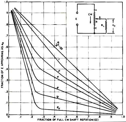
Fig. 1 - These curves show how the pot linearity varies with the load. By David L. Heiserman The linearity of a potentiometer can be completely changed by the position of the wiper arm and the resistance of the load. Most potentiometers used in communications and industrial electronic equipment are specified according to three characteristics: total resistance of the resistive material, maximum power dissipation, and the linearity of resistance as a function of shaft position. Both engineering technicians who must modify existing circuits and experimenters who are designing their own circuits face the problem of choosing the right potentiometer for the job at hand. As will be shown, this choice is not as simple as just selecting a likely looking pot from a catalogue. Selecting the appropriate pot is somewhat more complex than many people might be led to believe. The discussion that follows points out the problems involved in selecting potentiometers for loaded voltage-divider circuits and describes how to solve the problems using a few equations and the manufacturer's specifications. The circuit in Fig. 1 shows the conventional method of controlling the voltage across a load impedance RL. With this particular voltage-divider arrangement, a clockwise rotation of the shaft decreases the voltage applied to the load. If a linear voltage response is desired, the natural tendency is to choose a pot that has a resistive element specified as linear. The fact that the winding is linear, however, is no guarantee that it will produce a linear response under load. The curves in Fig. 1 show how the linearity of the output voltage changes with the ratio of load impedance to specified potentiometer resistance. When the load resistance is infinite (no load), the response of a linear pot is truly linear. As the load impedance decreases, however, the response becomes more non-linear. In theory, it is impossible to obtain a linear response from a linear taper pot that is loaded with any impedance. In practice, though, an RL/R ratio of 10 or more gives a response that is fairly linear. Likewise, a log taper pot will produce a truly log response only if the load impedance is infinite. As the RL/R ratio becomes smaller, the deviation from the specified log response becomes greater. When loaded, "voltage-divider" pots with certain non-linear characteristics will compensate for this undesirable loading effect and produce a nearly linear output. A discussion of non-linear pots, however, is beyond the scope of this article. Because of the unwanted effects of pot loading, the potentiometer resistance should be kept as low as possible with respect to the load impedance. However, a good linear response is bought at a high price - the smaller the specified pot resistance, the greater the current through its contacts and resistive elements. Power Dissipation The potentiometer power dissipation specified by the manufacturer is actually a reflection of the maximum current that can pass safely through any of the pot's three connectors or any portion of its resistive element. The following equation enables the user to calculate this maximum current rating: Imax = √(P/R) where Imax is the maximum amount of current that can pass safely through any part of the pot, P is the specified power rating of the pot, and R is the specified resistance of the pot. For example, a 10,000-ohm, 1-watt potentiometer can safely pass √[1/(1 x 104)] amperes, or 10 milliamperes. The current through a voltage-divider circuit such as the one in Fig. 1 is at a maximum when the wiper arm is in the position that makes the circuit strictly parallel (α = 0). The maximum current through any part of a loaded pot may then be determined by using the equation Imax = E [( R + RL) /RRL] where Imax is the maximum current through any part of the pot (at α = 0), E is the d.c. or r.m.s. value of applied voltage, and RL is the load impedance. Substituting Imax from this latter equation for I in the first equation, we find the relationship Preq = E2 [(R + RL) /RRL] where Preq is the maximum power dissipation of the pot. Example Suppose the d.c. or r.m.s, value of applied voltage (E) is 10 volts and the load impedance (RL) is 10,000 ohms. If a good linear response is desired, what are the necessary potentiometer specifications? Consider the linearity problem. The resistance of the pot should be no greater than 0.1 times RL, so we can select a 1000-ohm potentiometer. The maximum power dissipation of this pot in this circuit can be found by applying the second equation. In this case, Preq = 102 [( 10 x 103 + 1 x 10³) / (10 x 103) (1 x 10³)] or 0.1 watt. The specifications for this particular pot should be 1000 ohms, 1 watt, and a linear taper.
Posted April 15, 2024 |
|||||||||||||
 |
|||||||||||||
|
|||||||||||||

|
||||||||||||||||||||||||||||||||||||


