|
|||||||||||||
 |
|||||||||||||
Characteristics & Parameters of Coaxial Transmission Lines
|
|||||||||||||
Allen Kushner's (Times Wire and Cable) 1968 Electronics World magazine article portrays coaxial cables as essential microwave components with impedance, power-handling, attenuation, time-delay, and shielding traits that must hold steady over broad frequency, temperature, and harsh environmental conditions like moisture, corrosion, and flexing. Optimal use demands impedance matching for maximum energy transfer, minimizing VSWR, radiation losses, and delays; dielectric selection -- solid polyolefins/PTFE for moisture resistance versus low-loss foamed or air-spaced types with aluminum sheaths reducing attenuation by 20%; and superior shielding, from ~80 dB in single-braid to 110-plus-dB in doubles, triaxials, or sheathed cables. Electrical length, tied to propagation velocity (66% polyethylene, 81% foam), shifts with temperature (±1°), flexing, and frequency, critical for phased arrays. Mechanical compromises include stranded conductors for flex life (20% higher loss), tensile strength enhancements, moisture-proofing via pressurization/flooding, silver cladding for GHz stability, and precise, tested connector terminations avoiding soldering pitfalls. Coax excels in broadband efficiency; consult MIL-Handbook-216 for details. Characteristics & Parameters of Coaxial Transmission Lines
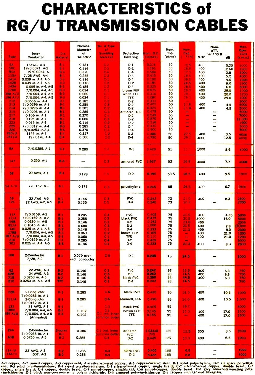
Table 1 - Characteristics of RG/U Transmission Cables. By Allen M. Kushner Coaxial cables are in every sense microwave components. They have an impedance characteristic, power capability, and a distortion requirement. transmission line is not just a piece of hardware; in reality it is a microwave component. It's not merely a cable which links two black boxes but a device with an impedance characteristic, a power - handling capability, an attenuation or distortion requirement, a time -delay characteristic, and a specific ability to provide electromagnetic shielding. In addition, coaxial cable must demonstrate these properties over wide frequency and temperature ranges without significant degradation due to exposure to moisture, corrosive environments, and mechanical abuse. Coax is not always the most efficient means of power transfer; but it is easy to handle and is effective over wide bandwidths. A valuable feature of coax is that the outer conductor also acts as a shield. To achieve maximum efficiency from coaxial cable transmission lines, the engineer must concern himself with: impedance- matching cables to the system or systems to assure maximum energy transfer; energy-loss or gain by radiation or pickup; insertion losses; and time delays. Mechanical considerations enter into his deliberations since tension and frequent flexing cause insertion losses, voltage standing-wave-ratios (v.s.w.r.) , and time delays to vary. Temperature and pressure in high altitude and underseas applications also affect insertion loss and power- handling capability: while exposure to moisture and chemicals influence cable life. Dielectrics
Fig. 1 - Cable losses due to dielectric configurations. The dielectric is normally a polyolefin, polytetrafluoroethylene, air, or some other substance. While air has excellent electrical characteristics, it is adversely affected by moisture and it does not provide the necessary support to maintain the center conductor in place with respect to the outer conductor. For a cable to have stable electrical characteristics, both factors must be kept constant. Solid dielectrics are not affected by moisture. they are easily bent without changing conductor spacing, and they are not affected by changes in ambient pressure. Offsetting these advantages, however, is the fact that solid dielectrics have the highest electrical losses (Fig. 1). Foamed-plastic dielectric is an effort at compromise between the solid-dielectric approach and the air-spaced cable. In foam-plastic dielectrics, a great many small, individual air spaces are obtained by releasing gas in the molten plastic during the extrusion process. But foamed dielectrics can absorb moisture and cause an increase in attenuation. This can be prevented by encasing the cable in a seamless aluminum tube. By doing so, a 20% or greater reduction in attenuation is achieved over ordinary solid -dielectric cables. It is apparent that we can reduce the attenuation even further by removing as much solid- dielectric material as possible, leaving only the amount needed to support and protect the center conductor. Cables housed in a seamless tubular aluminum sheath with the center conductor supported by minimum solid dielectric have the lowest possible losses for a given cable size. These sheathed cables are classified as semi- flexible since they may be easily bent for installation but not flexed in use.
Fig. 2 - In coax cables, electrical length changes with temperature. Some cable lengths will vary as much as 1°. Electrical Length Usually electrical length is not a crucial dimension but there are applications where the length of a coaxial cable is critically related to other elements and to the system as a, whole. Phased array antennas, for example, are functionally dependent on the electrical lengths of their various electrical members. Time-delay and electrical length are closely related and for many applications the engineer must know the mechanical length of the cable and the velocity of propagation of an electromagnetic wave through the cable (Fig. 2). Velocity is a function of the dielectric material. For example, solid polyethylene dielectric propagates at 66% of the velocity of light, solid Teflon 69.4 %, and foamed dielectrics at 81%. Air-spaced cables vary somewhat with velocities of propagation from production run to production run. In solid-dielectric cables, variances of ±1% are usual; foamed dielectrics ±2% and air-spaced cables ±2%. Electrical length also changes with cable flexing and frequency. The variation from a normal linear response can be ±1% in short cable lengths, but significantly higher where electrical-length spikes (variations at specific frequencies) occur in long cable runs. Shielding Energy pickup and leakage relate to the quality of the cable's shielding. It is important that engineers know how much energy is lost through radiation and how much is picked up from outside sources (interference). The specific application will, of course, spell out tolerances. For example, consider two N-foot lengths of single-shielded coax cable side by side. A one-volt input to one cable will result in approximately 10-4 volt induced in the second cable. This represents an over-all attenuation from cable to cable of 80 dB. This is only an approximation since much depends on the type of installation and surrounding conditions. But it is certainly a correct order of magnitude. In many systems, this much pickup is considered intolerable. Sensitive systems. therefore, use a second shield, triaxial cable, or a semi-flexible cable (aluminum sheath).
Fig. 3 - Relative shielding efficiencies for various cables.
Fig. 4 - Variation of v.s.w.r. with frequency. Narrow v.s.w.r. spike (2.11 was caused by bending the cable).
Fig. 5 - Impedance changes along the length of a cable.
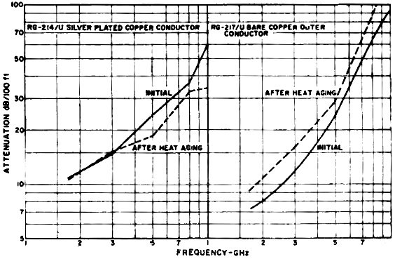
Fig.6 - A stability test of RG-214/U with silver-clad outer conductor and bare copper-covered RG- 217/U. Double-shielded cable generally adds about 15 dB more isolation; and triaxial cable about 15 dB more than the double shielded. Cables encased in seamless aluminum sheath are at least 80 dB better than the single-shielded flexible variety. The seamless metal sheath effectively stops energy from escaping or being picked up, except at the connector interface (Fig. 3) . Cables must also match the impedances of the "black boxes" they connect. Compatible characteristic impedances mean efficient transfer of power, no overheating, and no voltage breakdown. Characteristic impedance is a function of conductor size, dielectric material, and form (solid, foam, air); and uniformity of dimensions and velocity of propagation. A 0.1% impedance variation every 3 inches. The Mechanical Environment The mechanical environment in which a cable must work is also important in its selection by the designer. A cable chosen solely for electrical characteristics may be highly unsuited for its intended environment; and one picked for environment may have poor electrical characteristics. As it is with most engineering solutions, the result must be a judicious compromise between function and cost. For example, when a flexible cable with a solid conductor is attached to a shock-mounted piece of equipment or otherwise exposed to frequent motion. A stranded center conductor could be substituted. Characteristically, the stranded conductor will have a much longer flex-life than the solid, but the stranded conductor will have a 20% higher attenuation characteristic. The stranded conductor, however, is obviously the only practical approach and represents good engineering compromise. Tension Past installation practices generally account for cable design characteristics such as tensile strength. Cables of less than 1/8-inch diameter will usually break at about 100 pounds. Sometimes coaxial cables are used to support a component, in which case a strength member, such as a reinforced center conductor, a rated metallic, Dacron, or fiberglass member, is added. Usually, the limitation in cables over 1/8 -inch diameter is the method of cable termination. Moisture and Temperature Moisture affects the attenuation stability of cables. In a 1000-foot cable run it is reasonable to expect one or more pinholes which admit water vapor. Even if there were no pinholes, water vapor might enter the cable through the connector and condense. In the ground, borers or worms may attack the cable jacketing and thus permit water to be admitted. If the dielectric is foam. water vapor will cause an attenuation increase; and if it is solid, the water will eventually corrode the braid or short the connector. Underwater, the problem is even more severe because pressure can push the water through the entire cable length. Cables sheathed with seamless aluminum are less affected. Sheathed cables that use an air dielectric and a spline construction to protect the center conductor may be pressurized to prevent moisture entry. As long as the cable pressure is higher than the ambient pressure, the conductors will be immune to moisture and corrosion. New techniques developed for flexible and semi-flexible cables permit flooding the outer conductor with a corrosion prevention compound which does not affect the loss-characteristics of the cable. Since flexible cable jackets are not absolutely impervious to ambient moisture, corrosive vapors may also penetrate them and cause an in- crease in electrical losses with time. Flooding the outer conductor with a moisture-proofing compound is a good solution to this problem. Even aluminum-sheathed cables buried in the earth or otherwise subjected to corrosive ambients must be protected. Standard practice has been to extrude polyethylene jackets onto the aluminum sheaths. In a -new manufacturing technique, an additional corrosion preventative layer is added between the sheath and the polyethylene jacket. Elevated ambient temperatures may cause a permanent change in loss-characteristics by oxidizing the outer conductor. Therefore. attenuation in cables using bare copper and tinned copper conductors increase appreciably at frequencies above 1 GHz. Silver cladding of conductors brings attenuations down to acceptable levels (Fig. 6). Impedance and Mechanical Environment Even when the environment does not affect the cable proper, it may affect the cable-to-connector junction. The cable must at all times remain in intimate contact with the connector interface. Tension, flexure, temperature variations -all tend to destroy the contact. Temperature variations often cause some motion or shrinkage of the dielectric. Any such internal motions cause the cable-connector impedance and losses to vary. Sometimes, this kind of situation can go to extremes. A slight motion can. in certain cases, cause a v.s.w.r. of 3.0 and an increase in attenuation of 6 dB. These effects are most pronounced at the higher frequencies where a few thousandths of an inch of motion can mean significant alterations of cable characteristics and therefore significant changes in system performance. Cable Terminations All cables must be terminated in some manner. But the manner of termination becomes extremely important and relevant to system operation at frequencies about 1 GHz. Above this frequency, connectors of some kind are employed. But all the factors previously outlined or mentioned as leading to effective, efficient, and economic cable operation may be lost by use of an improper connector or by an improper termination procedure. Center conductors are normally soldered and sometimes. depending on application, crimped. The UG V-type of braid clamp is usually a part of the outer conductor; or it may be crimped or restrained between the two surfaces of a friction clamp. When using the UG -type clamp, care must be taken to form the outer braid over the clamping ring and to torque the back nut up snugly. With crimp-type devices, the crimp ring location is critical to both the attenuation and v.s.w.r. stabilities of the cable. Center conductor soldering is not really desirable because low temperature dielectrics (such as polyethylene) can over- heat and alter the relationship between inner and outer conductor at the connector interface. The cable must seat perfectly in the connector to achieve the designed electrical characteristics. If seating is off by as little as 20 to 30 thousandths, v.s.w.r. at high frequencies may increase. Also, above i GHz, cold-solder joints wreak havoc with cable parameters. There is increasing recognition of the importance and critical character of the interconnecting cable and its termination. The sophistication of the "black boxes" of today is too high to be sacrificed by an inadequate means of energy transfer. There is a trend, therefore, to purchase cable assemblies which have been fully tested for insertion loss and v.s.w.r. over the usable frequency range. Cable manufacturers have developed semi-automated techniques that replace the normal soldering processes as well as the UG -type of clamp and hand tools used in crimping operations. Many types of connectors are now being assembled to cables in a true precision machining process and, in most cases, each and every complete assembly is evaluated by vigorous tests over its entire specified performance range. Like so many other engineering areas, the design, manufacture, and application of coaxial cables has risen to the level of an independent technology. Nevertheless, it is still difficult to obtain enough cable design information to fully satisfy design needs. One of the best sources is MIL-Handbook-216, available to companies working on military contracts. Manufacturers catalogues are also excellent sources. Some cable fabricators issue technical memoranda from time to time which amplify specific topics of interest to cable users.
* The author holds a Bachelor of Mechanical Engineering degree from Rensselaer Polytechnic Institute and a Master of Science degree from the University of Connecticut. He is a former research worker for General Motors and also served with the U.S. Air Force as an Electronics Officer. |
|||||||||||||
 |
|||||||||||||
|
|||||||||||||


|
||||||||||||||||||||||||||||||||||||


