|
|||||||||||||
 |
|||||||||||||
Hi-Fi Crossover Networks
|
|||||||||||||
Since I am currently planning a loudspeaker configuration to replace the original speaker in my 1941 Crosley 03CB floor model AM / shortwave radio set, this article made for a good refresh on audio frequency crossover circuits. A very nice set of design charts is provided. Of course today there is no need to design and build your own since commercial units are very good and cost less than what I could build myself. Many moons ago while serving in the USAF at Robins AFB, Georgia, I did actually build my own crossover circuit for use in custom speaker cabinets I made in the base woodshop (they were sold years ago prior to a household move, unfortunately). The speaker that came in the Crosley has a 12" cone, which is still in good condition, but it uses an electromagnetic voice coil rather than a permanent magnet like modern speakers use. Using it would require rigging up a DC supply for it, which is too much trouble, and besides, the frequency response is nowhere near as good as a trio of bass, midrange and tweeter with a crossover. This article is Part 2, so I will try to get ahold of the first part in the April 1959 issue of Radio & TV News. This May 1959 Electronics World is the first after the name change from Radio & TV News (April 1959 being the final) Hi-Fi Crossover Networks
Advanced Acoustics Co. By Abraham B. Cohen & Paul D. Cohen / How to design and put together home-built precision networks for 2- and 3-way systems. In Part 1 of this article (in April 1959 issue), the principles behind the design of multi-speaker networks were generalized so that this article on the actual construction of the networks would not be interrupted by some of the more general thoughts concerning the application of networks. With the exception of the earlier reference to 6 db and 12 db attenuation per octave, a more complete treatment of the actual values involved in construction of a network was left for this part. Now we must deal a little more specifically with this matter of the 6 db versus 12 db roll-off characteristic of the network to determine the source of the particular values chosen. These are not arbitrarily selected values - they are specifically related to the values of the choke or capacitor element that will provide a given crossover point for a given impedance. Voltage Division at Crossover
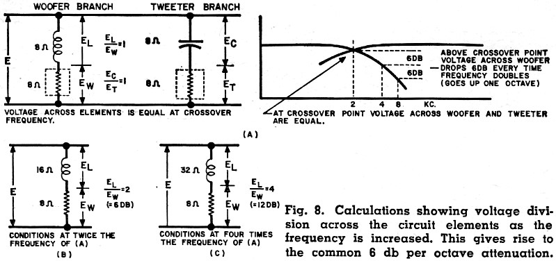
Fig. 8 - Calculations showing voltage division across the circuit elements as the frequency is increased. This gives rise to the common 6 db per octave attenuation. By definition, the crossover point is that frequency where the drooping output of the low-frequency branch of the network crosses over the rising characteristic of the high-frequency branch (as indicated in Fig. 3 of Part 1). For a 6 db-per-octave network, the value of the capacitor in the tweeter branch and the value of the choke in the woofer branch are chosen to provide an a.c. impedance across those two respective elements, at the crossover frequency, which will be equal to the speaker impedance. Fig. 8 shows a simplified circuit of a two-way network with a low-frequency branch and a high-frequency branch, both tied across a common voltage source. Let us assume that the speakers are both 8-ohm units and that it is desired to design a network to cross over at 2000 cps. We will have to find an inductor and a capacitor that will each present an impedance of 8 ohms at this frequency. Having found such components (more details later on actually finding these) and inserting them in the network of Fig. 8A, we see that the voltage in the low-frequency branch has been equally divided across the choke and the woofer. In a similar manner, the voltage across the high-frequency branch has been divided equally between the capacitor and the tweeter. Consequently, the voltage across the woofer is equal to voltage across the tweeter. This is the crossover point where the drooping low-frequency characteristic crosses the rising low-frequency characteristic. 6 db/Octave Attenuation Now we come to the matter of the octave rate of attenuation of these drooping and rising characteristics. Consider, first, the drooping woofer branch characteristic of Fig. 8A. If it a crossover frequency of 2000 cps the inductance in the woofer circuit is equivalent to 8 ohms, then at 4000 cps (one octave higher) this inductance will present a 16-ohm impedance since the impedance is directly proportional to the frequency. When this 16-ohm impedance is now considered in series with the 8-ohm woofer, Fig. 8B, then the voltage across the choke becomes twice that across the woofer. On a db basis (db = 20 log E2/E1) a 2 to 1 voltage ratio becomes 6 db. Thus, after the crossover point, the voltage drop-off across the woofer progresses at a rate of 6 db-per-octave. Thus, if we go up another octave the choke impedance doubles again, going from 16 ohms to 32 ohms, while the woofer still remains 8 ohms. The voltage in the woofer branch, Fig. 8C, is now at a 4 to 1 ratio. On a db basis, a voltage ratio of 4 to 1 represents a total drop of 12 db or, again, 6 db over the previous octave. The same analysis may be applied to the tweeter branch and it may be shown, in identical fashion, that the tweeter circuit capacitor, when necessarily chosen to be equal in impedance at the crossover frequency to the tweeter impedance will, below the crossover point, continue to roll-off at the gradual rate of 6 db-per-octave. So it is seen that the automatic 6 db rate of this type of network arises from the simple necessity of choosing reactive elements in the two branches to divide the voltages equally across the various elements in the circuit so that the individual speaker terminal voltages will be the same at the crossover frequency. 12 db/Octave Attenuation In Part 1 we discussed the general method of pairing off a capacitor with an inductance in each speaker circuit to convert a 6 db-per-octave network into a 12 db system. While "pairing off" is the general procedure, the values to be used in converting from a 6 db to a 12 db network need some modification. Thus, if a choke had been originally selected to have an impedance of 8 ohms at the crossover frequency (and equal to the. speaker impedance), then it would have to be multiplied by a factor of 1.41 when the systems were changed to a 12 db-per-octave network as indicated in Fig. 7 of Part 1. Similarly, the capacitance of the component which had been originally chosen for the tweeter circuit of the 6 db-per-octave network would have to be divided by a factor of 1.41 when the conversion is made. Once these new values have been determined by modifying the 6 db values, they may then be paired off to provide the 12 db network. Calculations similar to those in Fig. 8 may be made when using these revised values to plot out the network branch voltage which will drop at the rate of 12 db-per-octave after the crossover point when going in either direction. Inductance Variables It may seem that we put the "cart before the horse" in giving details on how to convert from a 6 db to a 12 db-per-octave network before we had discussed how to select the simple values for the 6 db network. However, since we had treated such conversion last month as part of the general philosophy of network design, it was deemed logical to carryover that discussion in terms of "numbers" so that a transition might be made to the problem of selecting real values of inductances and capacitances for a particular network. Of the basic elements found in the common network, the components such as capacitors and volume controls may be readily purchased, with the inductors not so widely available. However, this should prove no obstacle to the man who wants to build his own network. Invariably all instructions for building these chokes are predicated on "air-core" (non-magnetic core) design, for two reasons: first, air-core chokes completely eliminate distortion due to iron saturation and, second, laminations of a quality good enough for audio chokes are not easily obtained by the average home constructor. Wooden dowels, Masonite, and wires are, however, readily available. Easy as it is to build a choke, the initial design is far from simple. We cannot simply say that so many turns of wire constitute a given inductance. As a matter of fact, a given number of turns may yield widely different values of inductance depending upon the manner in which the turns are wound. The total inductance of a coil depends on the geometry of the coil. A long one-layer solenoid will have a far different inductance than a flat pancake coil of the same number of turns simply because the flux linkages of the various turns in one case are completely different than in the other. Even after having started with one given coil configuration, it is not a simple matter to guess what inductance a similar coil of more turns would be. It is true that, in general, the inductance is proportional to the square of the number of turns, but there are additional factors involved that determine the final inductance of the coil. For the purpose of this discussion, the inductance formula as derived by Maxwell was used in calculating the inductance characteristic of the coil. Building the Coil The practical reader need not become discouraged nor distressed at this point. The calculations have all been accurately carried out and checked on an actual model so the constructor may use these inductance values "as is." All he need be concerned about is the desired crossover frequency and the speaker impedance of his system. Chart 1 (on the fold-out page) supplies the basic details he needs to know about building the coil. These details include not only the number of turns, but the number of layers of wire, and, most important, the weight of the wire. It is discouraging to go out and buy a quantity of wire for an inspired evening of coil winding and then discover that you are short of wire.
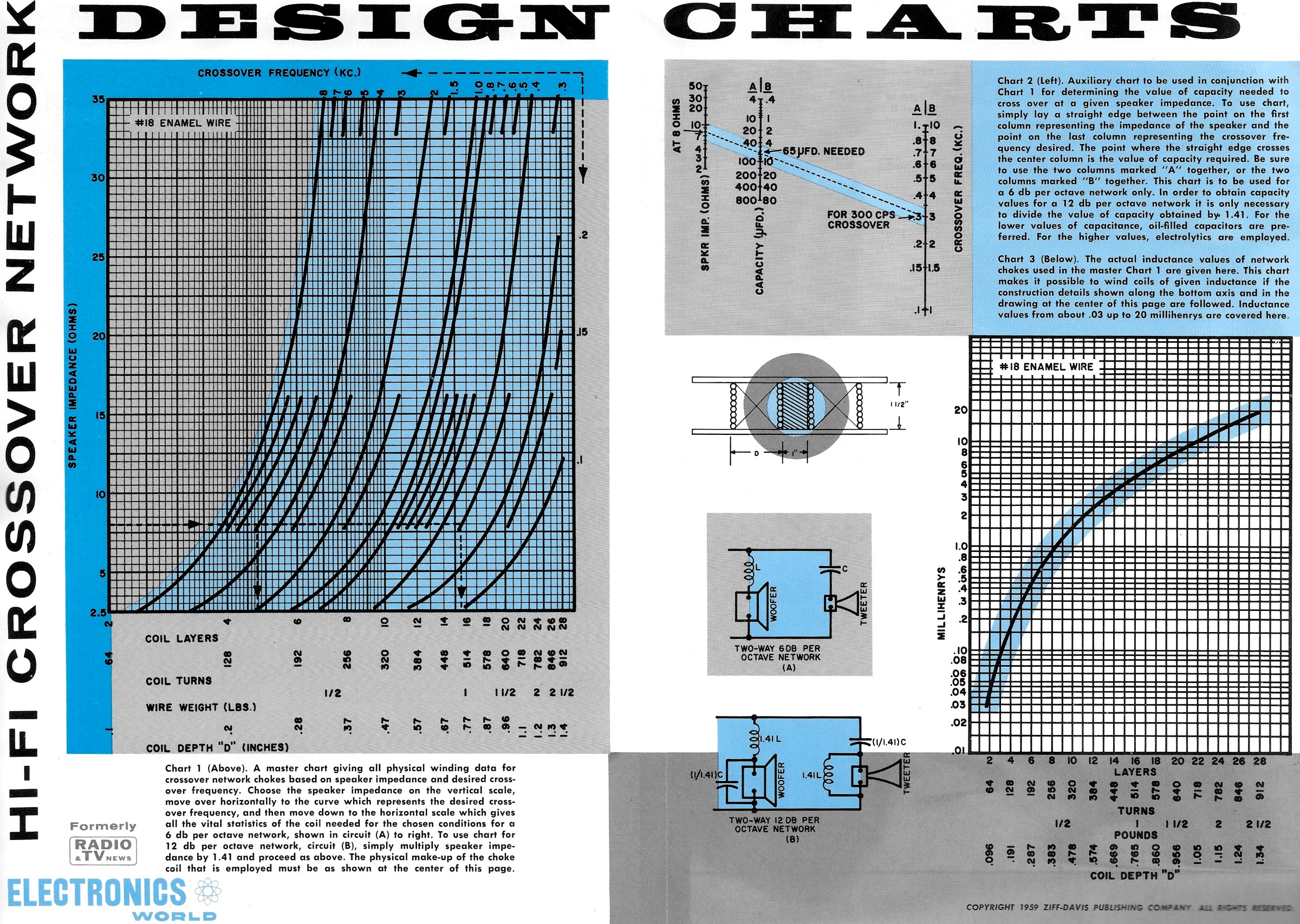
Hi-Fi Crossover Network Design Charts Although Chart 1 provides all of the practical details for making the coil for any given impedance and for any given crossover frequency, we have included another chart for the purist who still wants to know the inductance of his coil. If one were truly ambitious, he could wind one master coil with several taps along the depth for experimental purposes. Charts 1 and 3 give the actual curves of an experimentally checked master coil wound of #18 enamel wire on the coil form shown on the chart page. Along the abscissa are four scales: first, the number of layers, then the number of turns, then the pounds of wire that are necessary for a given inductance, and finally the coil depth. The coil form is made with a 1" wooden dowel as the core and the end pieces of hard 1/4" Masonite. A series of 1/8" holes were drilled along a radius of one of these end pieces so taps could be brought out anywhere along the depth of the coil. It is recommended that care be taken to insure that the coil is layer wound rather than random wound. Not only will there be considerable satisfaction in seeing a job well done but, what is more important, the final value of the coil will be more nearly correct for a given number of turns. Layer winding of the coil will be facilitated if separators of heavy fish paper or several layers of masking tape or sealing tape are interposed between every two layers of windings. Thus there will always be a comparatively smooth surface for the subsequent layers. It is suggested that the end Masonite pieces be secured to the center dowel by means of a brass bolt at least 2" long. This will permit the end of the bolt to be inserted in the chuck of a hand drill. The drill may then be held secure in a vise and the coil form slowly turned while the wire is guided onto the form by the drill handle. Using Chart 1 Chart 1 gives the details of the coil configuration for any desired frequency and speaker impedance. Choose the speaker impedance on the vertical scale, move over horizontally to the curve which represents the desired crossover frequency, and then move down to the horizontal scale which gives all the vital statistics on the coil for the conditions selected for a 6 db-per-octave network. To use Chart 1 for 12 db-per-octave networks multiply the value of the speaker impedance by 1.41 and proceed as above. This, in effect, increases the inductance value by 1.41 times, a requirement for a 12 db-per-octave network. The corresponding capacity to go along with the chosen inductance is easily determined. One may make a simple calculation of capacity by using the formula: C = 1/2πfXc. where f is the crossover frequency and Xc represents the reactance of the capacitor chosen to be equal to the speaker impedance at the crossover frequency. C will be the capacity required for the tweeter branch. Alternately, Chart 2 may be used to pick off the actual capacitor value for a given impedance at a given frequency. Here, again, as in the case of the coil, the value found for the capacitor is for a 6 db-per-octave network. For a 12 db-per-octave crossover, divide the capacitance value obtained by 1.41. Typical Three-Way Network Parts The very important matter of the type of capacitor to use deserves individual treatment, but consideration of this point will be deferred to the last so that we may illustrate the actual selection of component values for a typical three-way system. Let us assume an 8-ohm system with a crossover at 300 cps between the woofer and the mid-range and an upper crossover at 5000 cps between the mid-range and the tweeter. This system was shown in Fig. 7 of Part 1. The choke for the woofer is selected from Chart 1 by coming in from the 8-ohm point (speaker impedance) on the vertical scale to the 300 cps curve and then down to the horizontal scale where it is indicated that very nearly 16 layers (or 500 turns) of wire will be required on the coil form, that just under one pound of wire will be needed, and the coil depth will be approximately 3/4". This is all the information required for winding this woofer circuit coil. Now, the low-frequency blocking capacitor of the mid-range circuit will have to be equivalent in impedance to the speaker at the 300 cps crossover frequency. From Chart 2 the value of this capacitor turns out to be 65 μfd. Moving to the upper crossover frequency of 5000 cps, the high-frequency limiting choke in the mid-range circuit should have an impedance of 8 ohms at this frequency. Again from Chart 1, we select 8 ohms on the vertical scale, move horizontally to the curve representing 5000 cps, then vertically down the horizontal scale where we find that the coil will consist of 5 layers of wire (160 turns), will utilize approximately 1/4 pound of wire, and will be about 1/4" thick. The corresponding tweeter branch capacitor at this crossover frequency point will also have to have an impedance of 8 ohms and from Chart 2 this turns out to be 4.2 μfd. (call it 4). Thus all the details for winding the coils and choosing the right capacitor values are readily available if you know the speaker impedances and the desired crossover frequencies. To convert this network into the 12 db system shown in Fig. 7D, Part 1, the inductance values of the chokes should be multiplied by 1.41 and the capacities divided by 1.41 and then paired off as previously described. Type of Capacitors
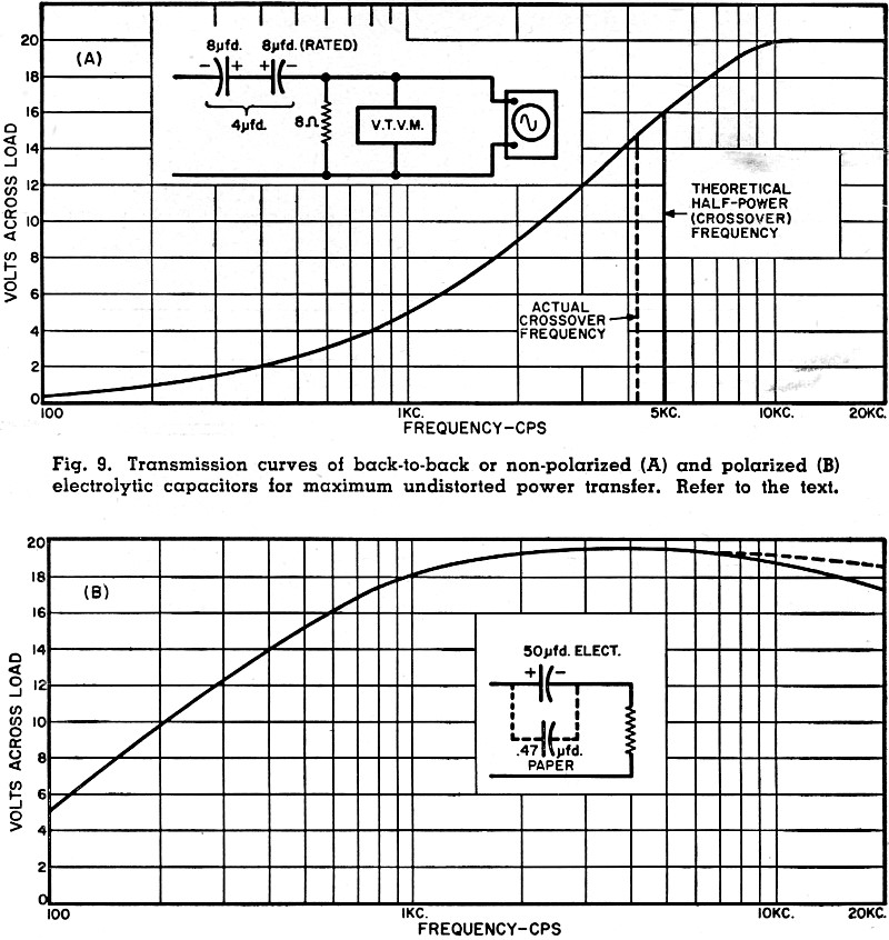
Fig. 9 - Transmission curves of back-to-back or non-polarized (A) and polarized (B) electrolytic capacitors for maximum undistorted power transfer. Refer to the text. We must now discuss the controversial question of the type of capacitor to be used in audio dividing networks. It has been generally conceded that one can't go wrong if he uses good oil-filled or paper capacitors. However, there is the matter of cost for such units. A 60 μfd. capacitor, even one rated at comparatively low voltage, may not fit one's pocketbook as well as it does the network data. This problem has been overcome in commercial equipment by using non-polarized electrolytic types where large capacities are required. These are comparatively cheap but they do have their shortcomings. In practice it has been found that the actual capacity of a batch of electrolytics, all rated the same but measured at the higher frequencies, may vary by as much as 25 to 30% from the rated value. In some instances it has also been found that the impedance of the non-polarized electrolytic may climb at the very high frequencies causing a tweeter loss. This latter loss may be easily overcome by shunting the electrolytic with a small paper capacitor, 1 μfd., for example, which will serve to keep the impedance of the capacitor section of the tweeter branch low at the high frequencies. The earlier question of the capacity variations is a more ticklish one. It is not generally possible to measure capacity before the capacitors are purchased. The next best thing is to buy two or three capacitors of the nominal rating and to select from these the one that comes nearest to the required impedance at the desired frequency. To make such a selection means, of course, the use of an audio oscillator, a voltmeter, and a potentiometer. With these items, an impedance substitution test may be made to determine which capacitor comes closest to the required value. It is desirable to choose one that is a little low in value since, if required, the value may be brought up to the proper capacity by shunting it with a small additional capacity which will aid the very high frequencies. Such closely controlled electrolytics have been successfully used in commercially available networks for many years and they have withstood the element of time very well. They have, however, been of the non-polarized variety, such as the motor-starting type. The hobbyist has had equivalent success by putting two electrolytics of the polarized type "back-to-back" to provide a non-polarized capacitor. Recently there has been discussion on the use of the simple polarized type of electrolytics for these audio networks and the writer approached the problem with some trepidation. On the surface, it seemed heretic to use a polarized element in an audio circuit that was to pass alternating waveforms unmarred and untarnished. However, in view of the fact that all these doubts could be resolved by definitive measurements, an analysis was made of the operation of polarized electrolytics and non-polarized electrolytics from the standpoints of reactance change, waveform distortion, and power transfer. The basic facts that were being sought were those concerned with the manner in which the waveform was passed through either type of electrolytic, the voltage rating of the capacitor, and the power to be passed on to the load by the capacitor. Tests were made at both low-level power and at high-level power with waveform and amplitude distortion observed on a scope over the entire audio spectrum. The non-polarized variety, made by backing up two standard polarized 8 μfd., 450-volt electrolytics, was tested first. A test run was made from 100 to 20,000 cps feeding this combination into an 8-ohm load resistor. Since these two 8 μfd. capacitors were connected in series back-to-back, their resulting capacity was 4 μfd. This value of capacity has a reactance of 8 ohms (to match the load at crossover point) at approximately 5000 cps. Under these conditions a frequency run was made of the maximum undistorted voltage that appeared across the 8-ohm load resistor, starting at 100 cps and proceeding to 20,000 cps. The output voltage of the amplifier was continually adjusted to give the maximum amplitude clean waveform at the load resistor, as seen on the scope. The plot of this run is shown in Fig. 9A. At the approximate crossover point, 5000 cps, there was the equivalent of 30 clean watts delivered to the load resistor, while at 20,000 cps this figure was 50 watts. This comes very close to expectations in that, at the crossover point, the power should be 3 db down from maximum. As indicated in Fig. 9A, the actual measured crossover point for these two electrolytics in series turned out to be 700 cps low (from 5000 cps) which would indicate that the electrolytic combination was about 13% off from rated value. What is of major importance is the fact that a full 50 watts could be delivered through such a back-to-back configuration of polarized electrolytics. Just to be contrary, the back-to-back direction was reversed so that where in the first case, the positive terminals were tied together, in the second case the negative terminals were connected. There was no change in performance. There is apparently no reason why non-polarized electrolytics cannot be used in crossover networks. But, now, how about the polarized type? With the same test setup as described previously, a test run was made on only one of the 8 μfd. units of the previous test. Again during the run the amplifier was adjusted to give the maximum undistorted waveform at the load resistor. The results were exactly the same as in the case of the non-polarized combination. There was no waveform distortion at a full 50 watts input to the load resistor and at the crossover point (in this case 2500 cps for 8 μfd. for 8 ohms) there was a clean 25 watts which was the expected 3 db down. To tie the matter down even more firmly, a test was made on three different 50 μfd. polarized electrolytics rated at 150, 50, and 25 volts respectively. No differences in performance could be observed as far as waveform at maximum output was concerned (50 watts). They were all clean, as observed on a scope. The last question that was to be resolved was the matter of the rising impedance of a large value of electrolytic at the higher frequencies, which would have the effect of reducing the voltage at the tweeter terminals. Fig. 9B is the curve of maximum undistorted waveform voltage at the load resistor from which it will be seen that for this 50 μfd. capacity, there is a drooping voltage characteristic at the load. When, however, this capacity was shunted by a small paper capacitor, the voltage characteristic was respectably evened out. Looking prejudice squarely in the eye, there would seem to be no reason as yet for not using electrolytics, polarized or non-polarized, for network construction. This, along with Chart 1 should make the matter of collecting the necessary components for a home-built network a fairly simple and straightforward operation. Chart 1 (Above). A master chart giving all physical winding data for crossover network chokes based on speaker impedance and desired crossover frequency. Choose the speaker impedance on the vertical scale, move over horizontally to the curve which represents the desired crossover frequency, and then move down to the horizontal scale which gives all the vital statistics of the coil needed for the chosen conditions for a 6 db per octave network, shown in circuit (A) to right. To use chart for 12 db per octave network, circuit (B), simply multiply speaker impedance by 1.41 and proceed as above. The physical make-up of the choke coil that is employed must be as shown at the center of this page. Chart 2 (Left). Auxiliary chart to be used in conjunction with Chart 1 for determining the value of capacity needed to cross over at a given speaker impedance. To use chart, simply lay a straight edge between the point on the first column representing the impedance of the speaker and the point on the last column representing the crossover frequency desired. The point where the straight edge crosses the center column is the value of capacity required. Be sure to use the two columns marked "A" together, or the two columns marked "B" together. This chart is to be used for a 6 db per octave network only. In order to obtain capacity values for a 12 db per octave network it is only necessary to divide the value of capacity obtained by. 1.41. For the lower values of capacitance, oil-filled capacitors are preferred. For the higher values, electrolytics are employed. Chart 3 (Below). The actual inductance values of network chokes used in the master Chart 1 are given here. This chart makes it possible to wind coils of given inductance if the construction details shown along the bottom axis and in the drawing at the center of this page are followed. Inductance values from about 0.03 up to 20 millihenrys are covered here. |
|||||||||||||
 |
|||||||||||||
|
|||||||||||||


|
||||||||||||||||||||||||||||||||||||


