|
|||||||||||||
 |
|||||||||||||
Side-Looking Radar Imagery
|
|||||||||||||
Side-looking airborne radar (SLAR) started out using a narrow beam formed by reflectors, like traditional radars, as opposed to the synthetic aperture type most often (maybe even exclusively) used today. Both types of side-looking radars rely primarily on the physical movement of the airborne platform for effective azimuthal scanning rather than steering the beam either mechanically or electronically. This 1965 Electronics World magazine article represents early versions which used "real aperture" antennas. Modern computer-controlled synthetic aperture radar beams can be segmented and directed off-axis for detected areas of interest as required, but the early systems simply gathered radar return data and presented it real-time, with some level of analog processing, to operators. Side-Looking Radar Imagery
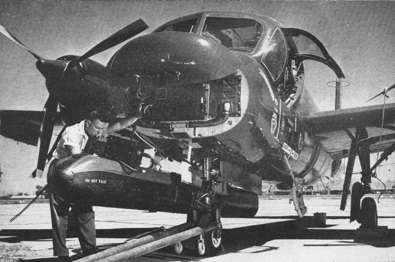
Fig. 1 - Side-looking radar installation on an Army Mohawk aircraft. Notice the long cigar-shaped radar antenna housing mounted beneath the fuselage. By J. L. Nelson Military Electronics Division Motorola Inc. Side-looking radars mounted in our military reconnaissance planes provide near-photographic mapping coverage in clouds and darkness. Imagery produced by electronic sensors, such as radar and infrared, is playing an increasingly greater role in the reconnaissance efforts of the military services. Such imagery not only supplements the aerial photograph, but in certain instances provides information that cannot be obtained by photographic techniques. For example, it has long been established that the ability of various types of electronic sensors to penetrate clouds and darkness as well as to map large areas is a most desirable characteristic. Side-Looking Radar An example of an electronic sensor currently used for mapping purposes is the AN/UPD-2 Side-Looking Radar System produced by Motorola's Military Electronics Division for the U. S. Army. The name "side-looking" stems from the fact that this form of radar collects mapping information from the terrain to the sides of the aircraft. In contrast, infrared and photographic systems are generally used to record terrain beneath the aircraft. Radar as a Sensor is a ranging device; its maximum range limit is approximately equal to the line-of-sight distance to the horizon. For example, an aircraft flying at 3,000 feet above the terrain is capable of mapping in excess of 50 miles to each side of the aircraft during a single run. It is not uncommon to map areas in excess of 30,000 square miles during the course of a single run, and this record may be contained on a strip of film less than 2 feet long. To better understand the structure of a radar image, the mechanics of the technique must be examined.
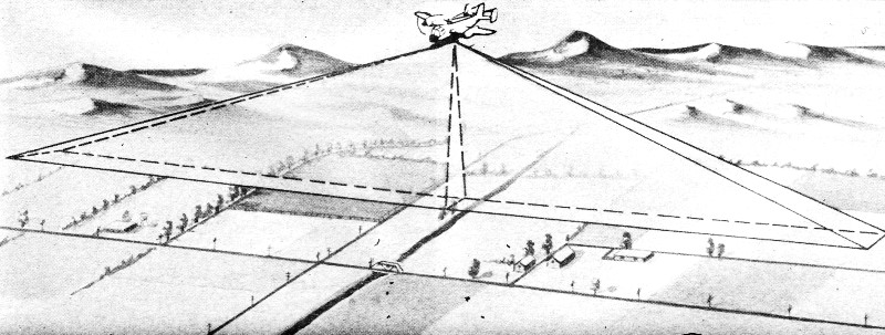
Fig. 2 - Geometry of a side-looking radar that has been installed on a reconnaissance aircraft.
Fig. 3 - Coverage patterns obtained with side-looking radar. (A) Pattern as viewed from above. (B) View from in front of plane.
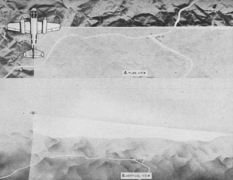
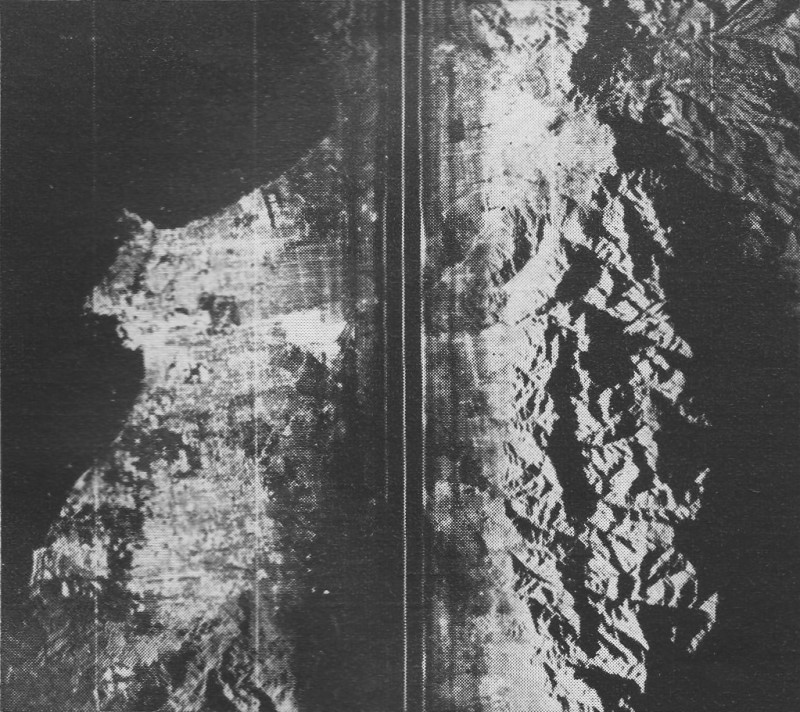
Fig. 4 - Side-looking radar imagery of Los Angeles area. The black central stripe which resembles a roadway directly below the plane is the aircraft's line of flight. Distortion Effects.
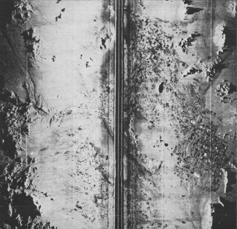
Fig. 5 - Side-look radar imagery of Phoenix, Arizona area. Notice the outward-going shadows on both sides of the center stripe resulting from radar beam illumination. Fig. 1 illustrates a typical side-looking radar installation in the Army's Mohawk aircraft. The cigar-shaped structure beneath the aircraft is the radar antenna. Fig. 2 shows the geometry peculiar to a side-looking radar. Note that the antenna pattern is a narrow fan-shaped beam extending from the aircraft outward to the horizon. In general, this beam is less than 10° thick; therefore, the radar illuminates and receives returns from only a narrow strip of terrain at anyone time. As the aircraft moves forward, successive strips of terrain are viewed by the radar system. As contrasted to a camera, a radar system does not examine the entire area contained in the strip at one time. It accomplishes its purpose by transmitting a high-energy pulse and recording the intensity of the return echo in synchronism with the time required for the pulse to reach a particular element of terrain and return to the aircraft. Thus, the basic terrain information is contained in terms of "range vs. time" as a video signal. This signal is converted to a film record by placing the video information on a cathode-ray tube as intensity modulation, sweeping the cathode-ray tube in synchronism with the radar return from each element of terrain, and photographing the resultant display. The film is caused to move at a rate proportional to the ground speed of the aircraft, thereby building up the map in synchronism with the illumination of successive strips of ground by the radar antenna. In general, the ground-scanning process may be likened to the scanning spot of a television raster. The process, as viewed from a point directly above the surveillance aircraft, is illustrated in Fig. 3. The narrow light area perpendicular to the side of the aircraft represents the geometry of the radar beam; hence the strip of terrain under surveillance. The area immediately aft of this beam represents terrain already mapped by the sensor. Examples of Imagery A typical example of imagery produced by a side-looking radar is shown in Fig. 4. The horizontal dimension is related to radar slant range. The black central stripe represents the range to the ground directly beneath the aircraft. Features such as roads, cities, farms, and other landmarks are readily discernible. Another example of a radar map made in the area of Phoenix, Arizona is shown in Fig. 5. Imagery such as that of Figs. 4 and 5 does not always lend itself to direct correlation with terrain maps or other systems of coordinates because of various types of distortion. Two prominent forms of imagery distortion often found in radar strip maps are: drift-angle distortion and ground-speed distortion. Taking first the case of an aircraft encountering a side wind, it will be necessary for the pilot to intentionally "crab" or yaw the aircraft to maintain the desired ground track. If the antenna is rigidly affixed to the aircraft for aerodynamic reasons, the beam will no longer be perpendicular to the ground track but will be rotated by an angle equal to the drift angle of the aircraft. In general, side-looking radar systems compensate for this by rotating the intensity-modulated line scan on the cathode-ray tube a proportionate amount, thereby providing first-order correction. To avoid ground-speed distortion, it is necessary to synchronize the motion of the film across the image plane to that of the aircraft over the terrain. In the event such synchronization is not achieved, the scale factor lengthwise along the film record will not be in agreement with the scale factor laterally across the film record. Thus, it is necessary that two vital pieces of information be provided to render proper coordinates on the final imagery. One device used for obtaining this basic information is a Doppler navigator. However, present Doppler navigators provide drift-angle and ground-speed information to accuracies on the order of 1 to 2 percent. After this information is further processed by the radar system, this error may be increased by another 1 or 2 percent. A number of higher order distortions are often apparent in a radar photograph. Such second-order effects as slant-range distortion and calibration accuracy and third-order effects such as cathode-ray tube and lens pin-cushion or barrel distortion, film shrinkage, and other factors may be present. Although a trained interpreter with suitable viewing equipment can often compensate for such distortions, the radar system design should minimize them as far as practical. For practical, day-to-day utility, a mapping radar requires other characteristics often overlooked by systems designers. Foremost among these is stability- freedom from drift of important parameters such as video gain, CRT intensity and focus, etc. Since the map is recorded photographically, it is not feasible for an operator to "tweak" controls to obtain optimum imagery. The future of radar holds much promise in improving radar surveillance imagery. Fig. 4 demonstrates the dramatic improvements in map realism now consistently obtainable through better scanning geometry, higher resolution, and longer grey scale. Further improvements in resolution could result from the use of shorter wavelengths and/or longer antennas. The first is negated by rain and fog attenuation and the second by aerodynamic considerations. The effects of long antennas can be synthesized by complex signal processing. Although such techniques hold the promise of future resolution improvements, equipment based on these principles is not yet dependable enough for field use by military personnel. |
|||||||||||||
 |
|||||||||||||
|
|||||||||||||

|
||||||||||||||||||||||||||||||||||||


