|
|||||||||||||
 |
|||||||||||||
Resistivity: Some Definitions
|
|||||||||||||
I have always found it annoying when an author uses a symbol or subscript in an article without explaining or somehow making obvious what it is. In this "Resistivity: Some Definitions" piece from a 1969 issue of Electronics World magazine, the author's stated purpose is to define terms related to resistivity, which he does well, but there are a couple instances where subscripts for resistivity, rho (ρ), are left for the reader to figure out. ρsp, ρs, and ρv have been replaced with ρspecific, ρsheet, and ρvolume , respectively, where needed. Sure, a careful reading of the surrounding content clarified the intent, but you are not supposed to work that hard. Otherwise, this is a great primer on the meaning of resistivity, how it is measured, and how it is used to calculate the resistance of a device. Caution is advised in noting and staying consistent with stated resistivity units when performing calculations. Resistivity: Some Definitions
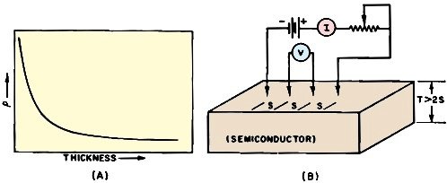
Fig. 1 - (A) In thin films, resistivity varies logarithmically. Four-point probe (B) is used to measure crystal resistivity. By Joseph Tusinski Often when defining technical terms or using them in an equation, many technical men confuse them and unknowingly employ wrong expression. Engineers as well as technicians some time have difficulty defining resistivity. Resistivity and resistance are both related to the ability of a substance to impede the drift of electronic charges. However, in specifically defining one or the other, dimensions used in formulating each term are either disregarded or not even considered. Resistance has dimensions of mass, length, time, and charge. Hence it is defined in terms of volts per ampere. The unit of resistance is the ohm and its symbol is capital omega (Ω). For example, when 100 Ω is expressed, what is implied is 100 volts per ampere. Resistivity, on the other hand, is given in terms of resistance per volume and its symbol is rho (ρ). Thus a problem normally involves resistivity when it appears in a formula and the wrong dimensions are used, or it would be more appropriate to say not used. Care should be exercised in using tables of resistivities because, in many cases, identical substances may have different numerical values of resistivity. Resistivity appears subscripted in a number of ways. Some are:
Lattice and imperfection resistivity deal with lattice vibrations and imperfections of a crystallographic structure. Hence technicians familiar with how semiconductors and thin-films are made will encounter these terms as well as sheet resistivity. Sheet resistivity may be encountered in a number of fields such as thin-film technology or microwaves.
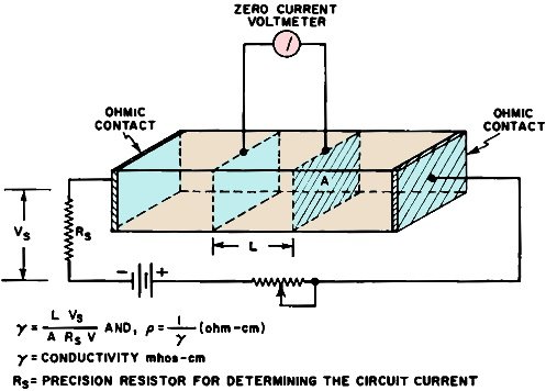
Fig. 2 - To measure bulk resistivity, current must be forced through the material and the resulting voltage drop measured. It should be mentioned here that all discussion about resistivity in this article refers to a homogeneous material. A heterogeneous material may be physically attainable or it may be obtained by virtue of frequency effects, such as skin-effect (see the author's article "What is Skin Effect?," June 1963 issue of this magazine). Fig. 1A shows that for very thin films, resistivity varies logarithmically and that for thicker materials, the resistivity curve flattens out. A four-point probe method (Fig. 1B) is used to measure sheet resistivity of semiconductor crystals. If the thickness of the crystal is more than twice the probe spacing, the resistivity of the material can be expressed by the equation: ρsheet = (2π Vs)/l where s = probe spacing, V = voltage measured with a zero-current voltmeter, l = constant current source, and 2π = 6.2832. Bulk resistivity, ρ∞, is another term used to describe the resistivity or the impurity concentration of a semiconductor. Ordinarily, when the resistivity of a material is measured, a known current is forced through the material and the resulting voltage drop is measured. Thus by Ohm's Law (R = E/I) the resistance is determined and related to resistivity in ohms/cm3. Very often the term is shortened to ohm-cm, the cube being implied. However, in bulk resistivity measurements, the resistance of the ohmic contacts must not be included in calculations. Thus a method somewhat similar to the four-point probe method is used (Fig. 2). Square resistivity is perhaps the most misunderstood of all. Technicians usually ask, "Square what?" or they assume that a square centimeter is implied. The implication of square resistivity is that the length of the sample is equal to the width, i.e., is square. Resistivities are given in ohms/square. For example, assume a sample of material having a resistivity of R ohms/square. Thus if four of the basic units are combined, the length doubles, hence the resistance doubles (2R); however, the width also doubles, which is the same as paralleling two resistors having values of 2R each. The total resistance of the combination is: 2R x 2R / (2R + 2R) = R. A simile can be derived by increasing the length three times and the width three times, i.e., square. The total resistance is: 1/(1/3R + 1/3R + 1/3R) = R. For example, suppose it is desired to achieve a resistance of 15 kΩ with a material having a resistivity of 300Ω/square. Let us assume that the resistor must have a minimum width of 20 mils: determine the length of the resistor. From R = ρsquare (L/W), L = WR/ρsquare then L = (0.02 x 15,000)/300, or 1 inch. This equation states that to determine the resistance of a specimen, the square resistivity is multiplied by the ratio of the length to the width. The use of specific, volume, and relative resistivities is normally relegated to metals. These are perhaps the most popular tables of resistivity available, and yet erroneous conclusions arise from their use. In electronics, copper wire has been the most popular material used to interconnect components. For this reason, many tables list the various characteristics of copper. However, the characteristics of copper may be altered by various means (alloying or annealing). Therefore a certain type of copper is used as a standard in evaluating the conductivities of materials (γ = 1/ρ). The standard, which represents 100 percent conductance, is annealed copper at a temperature of 20° C. The resistance of a one-meter-long section having a uniform cross-section of 1 mm is equal to 0.01724 ohm. Other methods were tried dealing with the weight of copper; however these were not too fruitful, and the measurement of length and area became the popular way to standardize. The conductivity of aluminum may vary by as much as 35 percent depending upon its composition. Pure aluminum (99.97 percent) has a conductivity of 64.6 percent of standard copper. Thus if standard copper is considered to be unity, aluminum has a relative resistivity of 1/0.646 = 1.54 or a specific resistance 1.54 times that of standard copper. Thus values derived from a table consisting of relative resistivities must be multiplied by the resistivity of copper to determine their actual or specific resistance. Tables relating the resistivity of a round copper wire were quickly formulated so that most of the arithmetic could be simplified. From these, a table of specific resistivities evolved. The popular dimensions chosen were the one -nail diameter and one-foot length (the mil-inch was adopted in England). Thus they yield the specific resistance of a material one-mil by one-foot, normally classified as Ω/mil-foot. For example, annealed copper would have a specific resistivity of 10.36Ω/mil-foot. Volume resistivities relate the resistance of a cubic structure. They are specified as follows: 1. Ω/cm-cube (preferred), 2. Ω-cm, and 3. microhm-centimeters. All three designations refer to a cubic specimen having square faces of one centimeter. The resistance is to be measured between flat plates making contact with opposing faces. Standard copper has a volume resistivity of 1.7241 X 10⁻⁶Ω/cm-cube or 1.7241 microhm-cm. When ρspecific, and ρvolume of copper are compared (1.7241 microhm-cm compared to 10.36Ω/mil-foot) and dimensions disregarded, serious mathematical errors result. A simple example will help to illustrate this point. The resistance of any uniform homogeneous material is given as R = ρL/A (ohms). It is obvious that if ρ = 1.64, or ρ =2.83 x 10⁻⁶, or ρ = 16.9 is used in the equation, different results would be obtained. However, all of these resistivities (relative, volume, and specific) are given for the same material. Thus in order for the calculated resistance to be meaningful, the units of L and A must be converted to correspond to the method used in determining the resistivity of the material. Another factor should be mentioned about determining resistivities of insulators. For example, the surface resistivity of an insulator is measured from the opposite edges of a square specimen. The bulk resistance of the body, which is parallel to the surface, must be many times greater than the surface resistance. The volume resistivity of an insulator must be determined using sophisticated guarding procedures, so that surface charges will not mask uniform conduction through the sample. All of the resistivities discussed are by no means all of the various forms of resistivity that the technician or engineer will encounter. The intent is to bring about a respect for a numerical value of resistivity and to be concise in specifying the dimensions, method used, or theory involved in determining a value of rho. |
|||||||||||||
 |
|||||||||||||
|
|||||||||||||


|
||||||||||||||||||||||||||||||||||||


