|
|||||||||||||
 |
|||||||||||||
A New Look in Transformers
|
|||||||||||||
Advances in transformer technology are driven by the need for miniaturization and efficiency, particularly in airborne and high-frequency military equipment. By optimizing core materials and fabrication, engineers can significantly reduce the weight and physical dimensions of transformers. A major technical milestone highlighted in this 1964 Electronics World magazine article, was the development of grain-oriented silicon steel, which, through precise crystal alignment, offers superior magnetic properties and reduced energy losses compared to traditional soft iron. Modern design further mitigates power loss from hysteresis and eddy currents by employing thin, insulated laminations, specialized nickel-iron alloys like Supermalloy for high-fidelity audio impedance matching, and high-resistivity ferrite ceramics for radio frequency applications. Today, the field of RF transformer technology has progressed far beyond 1960s-era methods, with modern designers utilizing advanced nanocrystalline and soft magnetic composite (SMC) core materials. These materials provide exceptional permeability and negligible eddy-current losses at very high frequencies, enabling even further miniaturization of components for today’s dense, high-performance electronic circuits. A New Look in Transformers
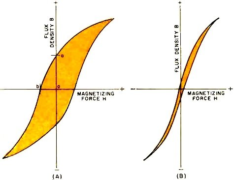
Fig. 1 - (A) Shows a typical hysteresis curve while (B) shows narrow -loop hysteresis curve preferred for transformer use. By John R. Collins New core materials and new fabrication techniques are making modern transformers smaller and more efficient. Transformers account for a very great part of the weight and size of most electronic equipment, so in this age of miniaturized components and printed circuits, a major effort is under way to shrink them to more compatible dimensions. The drive for improved efficiency has concentrated especially on transformers for airborne use with such success that these are now only a fraction of the size of the best available a decade ago. The materials and technology originally developed for airborne equipment, however, have found wider utilization, resulting in better transformers for less critical applications. There are many kinds of transformers, as reference to any catalogue will reveal. They are sometimes classified by application (as, for example, horizontal output, isolation, power supply), sometimes by operating frequency or power range (audio, i.f., r.f., high-voltage) , and sometimes even by method of construction (hermetically sealed, toroidal). All types, however, can be conveniently grouped under a relatively few functions: step-up or step-down of voltage, impedance matching, circuit isolation, or phase inversion. Even though only one function is of interest for a particular application, other functions may be performed as well. Thus, an output transformer, intended primarily for impedance matching, will also step down the voltage, invert the signal, and isolate the speaker from the tube. Power Transformers Power transformers are used to convert a supply voltage to the proper value for input to rectifiers, and sometimes to supply filament voltage. They are made in a range of values from a few watts to several megawatts. Although in the United States most power transformers are designed for 60-cycle operation, in recent years 400-cycle transformers have found increased use, especially in military and airborne equipment where weight and size are critical. Developmental work has also progressed on models for 800-cycle and even higher operation.
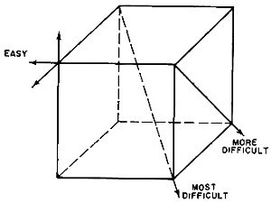
Fig. 2 - A cubical silicon steel crystal showing relative difficulty of magnetization along the various crystal axes.
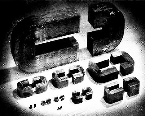
Fig. 3 - "C" cores made from 3% grain-oriented silicon steel can be used with flux densities from 15,000 to 17,600 gauss.
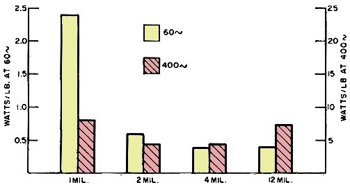
Fig. 4 - Core losses for grain-oriented silicon-steel cores of various thicknesses operated at 60 and 400 cps, 10,000 gauss.
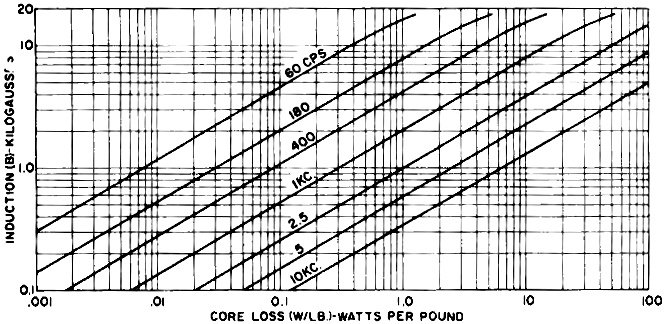
Fig. 5 - Core loss in watts per pound at various operating frequencies for 4-mil, grain-oriented silicon-steel "C" cores.
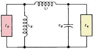
Fig. 6 - Audio transformer equivalent circuit. The interest in higher frequency transformers stems from the fact that for equal power, the minimum size of a transformer is inversely related to its operating frequency. A transformer for 25-cycle operation, for example, must be about twice the size of a 60-cycle transformer of equal power. At 400 cycles, the minimum size will be far smaller. However, the reduction will not be in exact proportion to frequency because of increased losses which limit the savings that might otherwise be effected. A major source of power loss is hysteresis, which results from the tendency of the core to retain flux (called residual magnetism) after magnetizing force has been withdrawn. In a.c. circuits, therefore, power must be expended to overcome residual magnetism each time the current reverses. In a typical hysteresis curve (Fig. 1A), line oa represents the residual magnetism when magnetic force is zero. Line oh represents the force which must be exerted in the reverse direction to reduce flux to zero before magnetization in the opposite direction can take place. Power lost through hysteresis represents wasted energy, the amount of loss being proportional to the area enclosed by the hysteresis loop. For this reason, materials having a narrow loop, as in Fig. 1B, are preferred for transformer use. Since the hysteresis loop is retraced with every cycle, losses become very appreciable as the excitation frequency is increased. Eddy currents induced in the core by the magnetic field are another cause of power loss. These currents may be counteracted by constructing the core of thin laminations of metal which are insulated from each other, and by using materials of low conductivity. Power lost through hysteresis and eddy currents is expended in heating the core. Early transformers were relatively inefficient devices which were built large not only to accommodate the necessary flux but also to provide enough area to dissipate heat. The first step in making better transformers was to develop better core materials capable of accommodating more flux without becoming saturated and having small hysteresis and eddy current losses. Originally, soft iron used for cores had a permeability of only about 5000. Permeability was increased through purifying the metal until a figure of about 35,000 was obtained. Although iron of much higher permeability was achieved in sample cores, it was found that these were generally too delicate for practical purposes. The presence of a few percent of silicon was found to substantially increase the resistivity of iron and thus cut down eddy-current losses. Silicon iron or steel is now almost universally used for power transformers, although some developmental work has been done on transformers using alloys which utilize aluminum instead of silicon. For many years, steel sheets 14 mils thick and containing 4% silicon were standard for transformers, and these provided excellent service for most purposes. A good 4% silicon -steel core, for example, will have a loss of about 0.8 watt per pound at 60 cycles and 12,000 gauss. Its losses become prohibitively high, however, with increased frequency. Grain-Oriented Steel The development of grain-oriented silicon steel was a major breakthrough in transformer technology. This process resulted in steel with greatly reduced hysteresis loss, permitting the operation of transformers at 400 and 800 cycles. The great savings in weight and size, previously theoretically possible, thus became an actuality. The grain-orientation process can be understood by referring to Fig. 2 which represents a cubical crystal of steel. As depicted here, steel can be readily magnetized in the directions of the cube edges, but with greater difficulty along any diagonal. Grain-oriented steel is made by a combination of cold-rolling and heat-treating techniques which align most of the crystals with their edges parallel in all directions. The resulting product, which usually contains 3 to 3.5% silicon, has magnetic properties far superior to hot-rolled steel. It is readily magnetized across as well as along the sheet, a fact which gives far lower energy losses and greater flexibility in designing transformers. Once it has been properly heat-treated its characteristics do not change, so that the transformer will not age with use. Fig. 3 shows various sizes of "C" cores fabricated from grain- oriented silicon steel by the Arnold Engineering Company. These cores have high saturation flux density and lower core losses than any types made from regular silicon steel. They can, therefore, be operated at high frequency and with unusually high flux density. These factors lead to smaller, lightweight transformers. Core Fabrication In practice, core material is cut into strips or tapes and is chemically treated on both sides to provide resistance between laminations. The tape is then wound on mandrels to form gapless cores. The cores are then annealed to relieve winding stresses. In some cases they are varnished to provide greater rigidity and ease in handling, after which they are cut in two. This is a precision operation which results in core halves that can be fitted together with a maximum air gap of only about 0.001 inch. The effect of an air gap in a magnetic circuit is similar to that of a resistor in an electrical circuit. It offers opposition to passage of flux, just as a resistor opposes current. Since the permeability of air is only 1, compared to 35,000 or more for silicon steel, it is apparent that the effective permeability of a magnetic core may be considerably reduced by even a relatively small air gap. For very critical circuits, toroidal cores which are formed in the regular way, but are not cut, may be used. Special machines are needed to wind coils on toroidal cores. The thickness of sheet to be used is determined principally by the frequency of operation. Although it might be expected that the thinnest sheet would always be best, this is not the case, as shown by Fig. 4. For 60-cycle use, 12-mil, grain-oriented silicon steel is equal to 4-mil and superior to either a 2-mil or 1-mil sheet. For 400 cycles, however, the 4-mil and 2-mil thicknesses are much superior. Fig. 5 shows how core loss varies at different flux densities and frequencies for one type of 4-mil core made by the Arnold Engineering Company. Even though the loss in watts per pound is substantially greater at high frequencies than at 60 cycles, the fact that a smaller core can be used offsets this difference, so total losses may not be greater. It must be remembered, furthermore, that it is usually more important to conserve weight than power in a high-frequency power transformer. Very large power transformers are often liquid cooled, but transformers for electronic circuits are usually air cooled. In miniature transformers, heat is concentrated in a smaller area, so the operating temperature is usually higher than for larger models. Where weight is an important factor, it has proved best to build small, compact transformers and simply let them run hot. This means, of course, that better insulation must be used on wires. Recently, insulations including asbestos, Teflon, and certain ceramics have been utilized, and high-temperature transformers have been produced capable of operating at hot-spot temperatures to 600° C. Such transformers can not be used in conventional areas, but only in special applications where such high temperatures can be tolerated. In recent years, there has been an increasing demand for high-fidelity audio transformers to match the high impedance of the amplifier power stage to the low voice-coil impedance, with essentially linear response over a frequency range from about 20 to 20,000 cycles, and higher. The difficulty of achieving this end is illustrated in Fig. 6, where primary and secondary transformer impedances are represented by Zp and Zr, respectively. The inductance of the primary is represented by Lp. And, it is obvious that Lp must be high to prevent a low-resistance shunt across the primary impedance. Inductive reactance decreases as frequency decreases, and unless LF is large, low-frequency response will be poor. On the other hand, leakage reactance (L1) and distributed capacity (Cd), control the high-frequency response. As frequency increases, the reactance of L1 increases and offers series opposition between primary and secondary. At high frequency, Cd becomes a low-reactance shunt for the secondary impedance. The simplest way to obtain the high primary inductance needed for good low- frequency response is to increase the number of turns on the primary. Unfortunately, this procedure results in greatly increased leakage reactance and distributed capacity, and thus poor high-frequency response. The solution to the problem is to use core materials with exceptionally high permeability. In recent years, various nickel-iron alloys, known under the general name "permalloys," have found increasing use in audio transformers. One of the best is Supermalloy, which contains 79% nickel and 5% molybdenum, and has maximum permeability of about 1,000,000. With higher permeability core material, fewer turns on the primary will provide the required high inductance leading to smaller leakage inductance and markedly reduced distributed capacity. Special winding methods have been devised to further reduce these effects. With careful design, transformers are now made with thin, high-permeability alloys which are essentially flat over the entire audio range and for some distance beyond it. Pulse Transformers Pulse transformers are basically impedance -matching devices developed originally for radar to permit the coupling of the pulse modulator output to a 50-ohm cable and the 50-ohm cable to the input of a magnetron tube. For this purpose, transformers capable of handling power up to about 50 megawatts are now in demand, and these may weigh several thousand pounds. At the other end of the scale, small, toroidal-type pulse transformers are needed to handle the pulses in logic circuits of digital computers. Although high power levels obviously introduce special insulation problems, the basic problem is the same in both cases: to design transformers capable of passing square pulses of short duration without distortion. Rise time of the leading edge must be short and decay time of the trailing edge brief to permit high repetition frequency. These requirements imply a wide bandwidth. Cores for pulse transformers are normally made of 1- and 2-mil magnetic materials, either grain- oriented silicon steel or nickel-iron alloys. Windings are usually interleaved (that is, either the primary or the secondary winding is divided into two sections and the other winding is placed in between) to reduce leakage reactance. In larger cores it is customary to leave an air gap to reduce the residual magnetism resulting from the fact that magnetizing force is applied in one direction only so there is no opposing demagnetizing force as in the case of an a.c. field. Powder and Ceramic Cores At radio frequencies, the use of either silicon steel or nickel-iron alloys becomes impractical, primarily because of eddy currents. In early equipment, air-core transformers and coils were used exclusively at radio frequency. Now, however, magnetic metals are reduced to fine particle size, coated with an insulating substance, and embedded in a resin to make cores for r.f. use. Both silicon steel and nickel-iron alloys are used in this manner, permitting substantial reduction in size of components as well as improved operation. I.f. transformers which in standard broadcast-band receivers operate at 455 kc., are among the principal types employing magnetic powdered cores. In recent years, a class of ferromagnetic ceramics called "ferrites" has become increasingly important as core materials for r.f. use. Their chemical compositions have the general formula XFe2O4, where X may be any of a number of metals. Manganese, nickel, and zinc, either singly or in combination, are most commonly used for transformer cores. Ferrite cores characteristically have permeabilities from about 100 to 2000. Their resistivity is extremely high, so it is unnecessary to laminate or powder them to reduce eddy current losses. They are employed in broadband, untuned transformers for communications equipment, where air-core coils are too inefficient for practical use. Used as cores for i.f. transformers, ferrites allow these devices to be made in sizes commensurate with transistor circuitry. Probably their greatest application, however, is for flyback transformers in television receivers, where they represent a substantial savings over the very fine magnetic metal cores that would otherwise be required. Their high resistivity makes them particularly useful, especially at the higher frequencies. |
|||||||||||||
 |
|||||||||||||
|
|||||||||||||

|
||||||||||||||||||||||||||||||||||||