|
|||||||||||||
 |
|||||||||||||
Traveling Wave Tubes (TWTs)
|
|||||||||||||
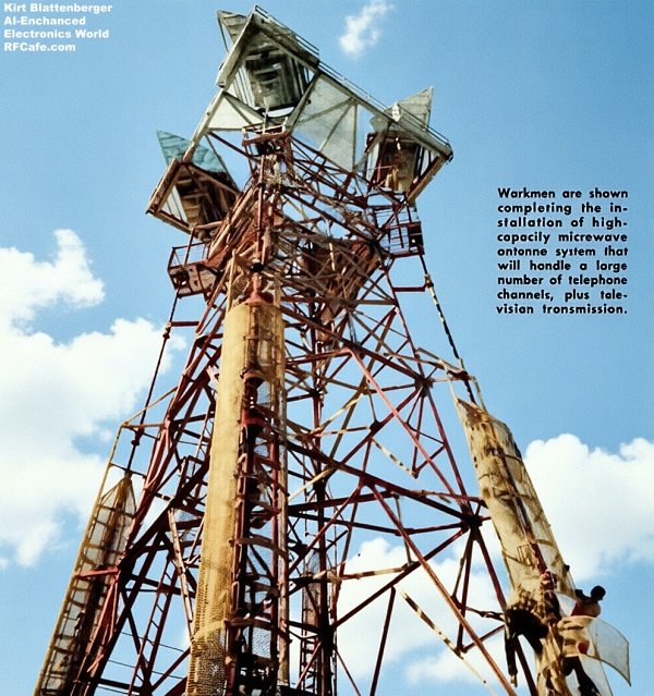
AI-Generated version of transmission tower shown below. The traveling-wave tube (TWT), invented by Dr. Rudolph Kompfner during World War II, revolutionized microwave amplification by providing exceptional bandwidth without the limitations of traditional resonant cavities. By utilizing an electron gun, a precision-wound helix, and a magnetic focusing circuit, the TWT transfers energy from an electron beam to a propagating signal wave. This design enables high-gain, low-noise performance essential for radar, missile guidance, and high-capacity telecommunications systems like the TH radio-relay. Although early production faced challenges regarding reliability and manufacturing complexity, ongoing engineering refinements achieved the stability necessary for critical applications, including the Telstar communications satellite. Today, TWTs remain vital in specialized high-power and wideband applications, including satellite transponders, electronic warfare platforms, and advanced radar systems, where they continue to offer performance benchmarks that solid-state alternatives often struggle to match in demanding high-frequency, high-power environments. Traveling Wave Tubes (TWTs)
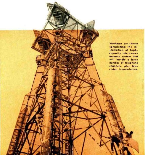
Workmen are shown completing the installation of high-capacity microwave antenna system that will handle a large number of telephone channels, plus television transmission. By John H. Jarrett, Widely used in present microwave communications systems, radar, and missile -guidance because of their outstanding performance as very wide -band, very low -nose amplifiers, these tubes will play an even more important role in future space communications. Today's traveling-wave tubes are increasing the capabilities of communications tremendously. They are making possible the handling of a greater number of long-distance telephone calls as well as color and black-and-white TV signals. They are also performing superbly for our Armed Forces in the command- guidance systems developed for "Nike Hercules" and the "Titan" ICBM. Not long ago, the "Telstar" communications satellite was placed into orbit around the earth where its outstanding performance has demonstrated the feasibility of satellite communications. It, too, contains a traveling-wave tube designed and constructed specifically for this spectacular application. As is the case with most new designs, there have been many problems associated with this device, some of which are: short operating life, unstable operation, high manufacturing cost, and installation and replacement difficulties. Correction of these conditions is well underway and has resulted in tubes which can hold their own with more conventional electron tubes in reliability. Reliability and uniformity of this product depend on sound engineering design, while the precise mechanical construction required depends on carefully tailored manufacturing facilities.
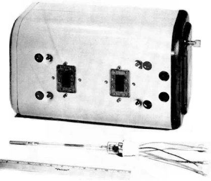
The 444A traveling-wave tube, slightly less than a foot long, is shown in front of its housing assembly. The input waveguide flange is at the right and the output flange is at the left.
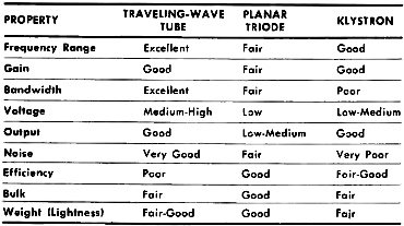
Table 1 - Properties of three types of microwave TWTs.
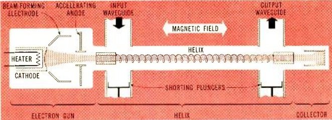
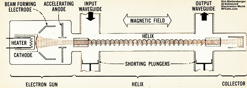
Fig. 1 - Simplified diagram of the traveling-wave tube, showing electron flow (top: original, bottom: AI-enhanced).
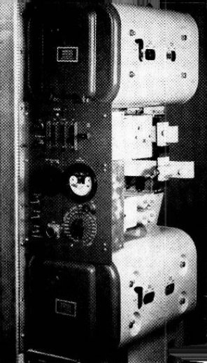
A portion of the broadband radio transmitter used in the TH microwave radio-relay system. Traveling-wave tubes are contained within the housings at the top, bottom of photo.
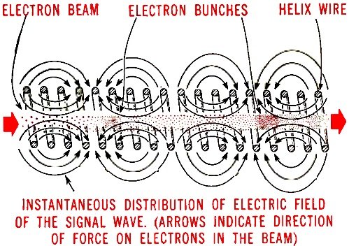
Fig. 2 - Interaction between electron beam and helix fields in a TWT.
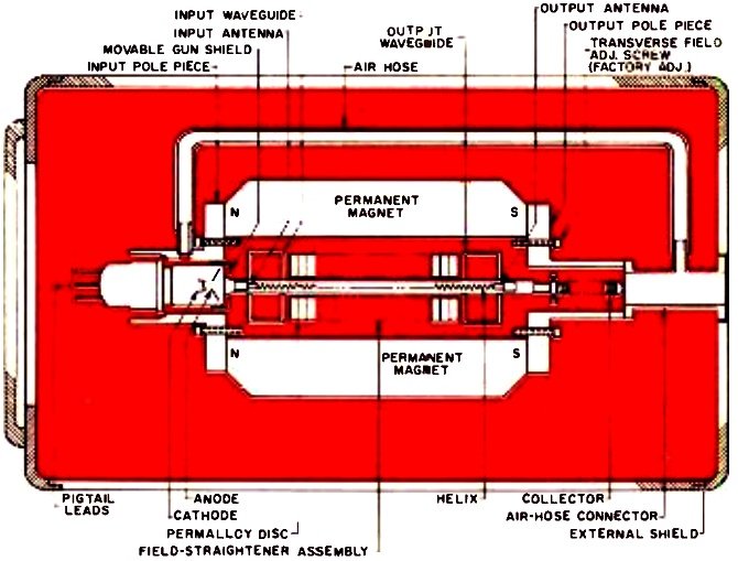
A cross-section of TWT tube with magnetic circuit in housing.
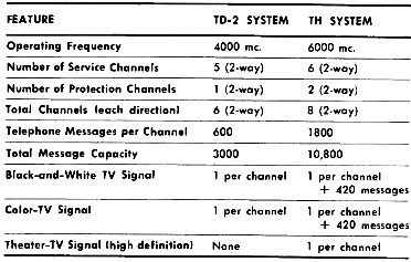
Table 2 - Capacities of TD-2 and TH radio-relay systems.
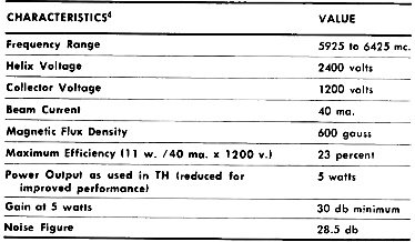
Table 3. Main characteristics of 444A traveling-wave tube.
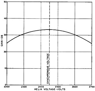
Fig. 3. Variation of the circuit gain with helix voltage.
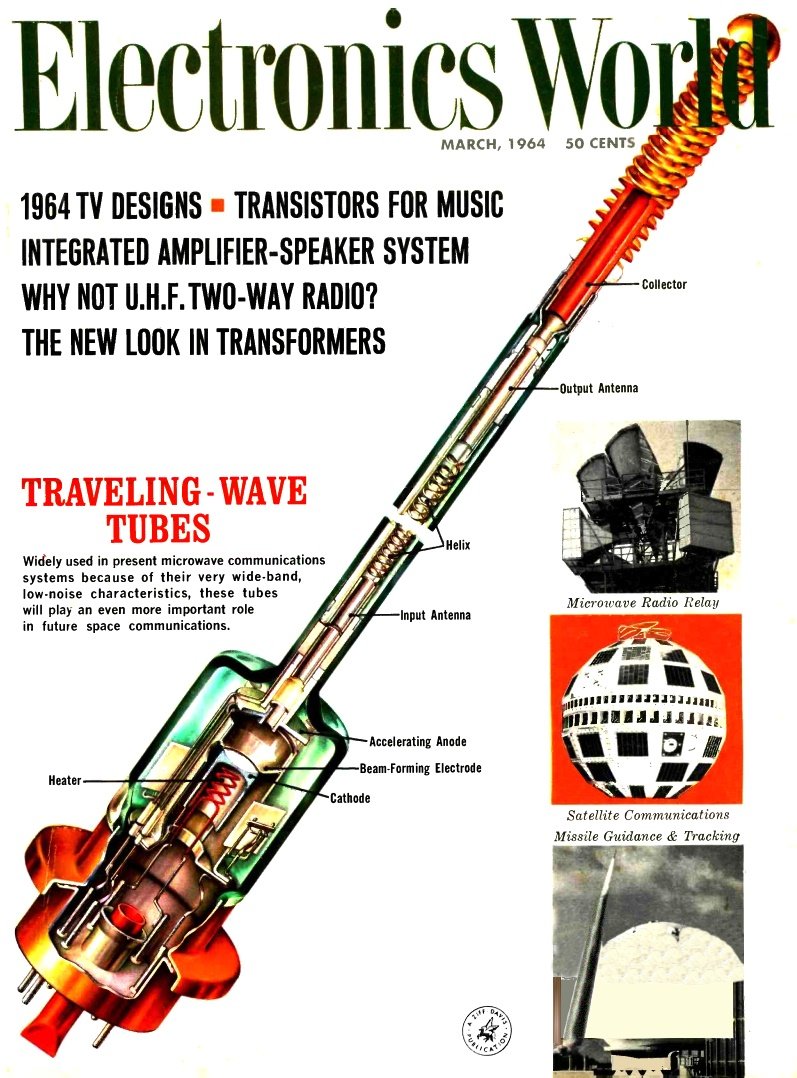
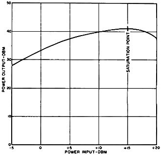
Fig. 4. Output power of the TWT plotted against input. Traveling-wave tubes, like more conventional types, can be designed for a variety of their use as c.w. power amplifiers, as low-noise amplifiers, and as high-gain pulse amplifiers. Background The traveling-wave tube (TWT) was invented by Dr. Rudolph Kompfner, now of Bell Telephone Laboratories, during the World War II period. While with the Physics Department at Birmingham University (1941 -1944), his concern for what he considered to be a weakness in the klystron led to his invention of the traveling-wave tube1. This weakness was the relatively narrow bandwidth of klystron amplifiers. The importance of his invention was soon realized and intensive development work has been carried out in many laboratories to bring the tube to its present practical state of development. Theoretical studies by Dr. J. R. Pierce of Bell Telephone Laboratories established certain basic design considerations for this type of electron tube from which numerous practical tubes have since been developed. Table 1 illustrates significant property comparisons among typical traveling-wave tubes, planar triodes, and klystrons, all designed especially for microwave use. The basic feature which characterizes all traveling-wave tubes is that amplification occurs gradually along an extended waveguiding circuit adjacent to an extended electron stream, with energy transferred from the electron stream to the signal wave propagating in the circuit. Thus, use of the bandwidth26 limiting resonant cavity, as in a klystron, is avoided - along with its attendant operational problems. How It Operates Basically, the traveling-wave tube amplifier consists of a magnetic circuit and an electron tube. The magnetic circuit may be in the form of a solenoid, permanent magnets, or a periodic permanent -magnet structure, along with its associated input and output waveguides or coaxial cables. The magnetic field produced by these magnetic structures is used to focus the beam of electrons. Normally, the electron beam traveling through the helix along its longitudinal axis would tend to disperse itself due to the combined influence of the mutual repulsion of electrons and attraction resulting from positive operating voltage on the helix. The magnetic field, consisting of uniformly controlled lines of force, threads through the helix along its axis to focus the beam of electrons by spiraling the electrons - which try to reach the positive-voltage helix - back toward the center of the beam. This action permits the electron beam to be transmitted through the helix without appreciable interception of electrons by the helix so that amplification of the input signal may occur. If electrons were allowed to freely impinge on the helix they could cause serious deterioration of both efficiency and tube life. The input and output waveguides, or in some cases coaxial cables, serve to carry the microwave signal to be amplified to the helix of the electron tube; and, after amplification by the tube, from the helix for further use in the microwave system. The electron-tube portion of the traveling-wave tube amplifier can best be understood by considering its three major sections individually: gun, helix, and collector. The electron gun provides the precisely shaped electron beam that travels through the helix to impart energy to the radio signal to be amplified. Basically, the typical simple gun consists of a heater, a cathode, a beam-forming electrode, and an accelerating anode. Electrons are accelerated from the heated cathode by voltage on the anode and, as a result of the focusing action of the beam- forming electrode, enter the helix in a dense, narrow, circular cross- section beam. This beam then travels through the helix to the collector which is at a positive potential with respect to the cathode and, therefore, collects the energy of the unused beam. The traveling-wave tube shown in the simplified diagram of Fig. 1 (see also the cover illustration) is typical of the designs which have been manufactured by Western Electric Company. The heart of this type of TWT is the helix, which visually resembles a helical spring but which is normally much smaller in diameter and wire size and is precision made. The signal to be amplified enters through the input waveguide and is picked up on the antenna at the gun end of the helix. From there it travels at nearly the speed of light around the helical path of the helix wire until it reaches the antenna at the collector end of the helix. The amplified signal is radiated from this point and leaves the amplifier through the output waveguide. Although the signal wave travels along the helix wire at nearly the velocity of light, its forward motion along the helix axis is much slower - on the order of about one-tenth the velocity of light. The electron stream is made to travel from the electron gun through the helix, by means of an accelerating electrode, at a slightly faster rate than the signal wave. It is the interaction between the electron stream and the electric field of the signal wave that amplifies the natural wave signal. The interaction between the electromagnetic wave of the microwave signal and an electron beam is qualitatively illustrated in Fig. 2. The pattern of arrows indicates the instantaneous distribution of the electric field of an electromagnetic wave traveling along the helix. At points corresponding to wavelengths (measured along the helix) the direction of the arrows reverses. The field pattern progresses with a phase velocity depending on the diameter and pitch of the helix. If all the electrons in the beam are moving at the same velocity, it can be seen that some electrons are in an electric field which tends to oppose their motion while others are in the opposite condition. Therefore, as the electron beam and the electromagnetic field move along together, a form of "electron bunching" occurs as the faster electrons overtake the slower electrons ahead of them2. As the bunches of electrons are slowed down, the kinetic energy they lose is gained by the fields of the wave. Hence, the wave gains energy at the expense of the electron beam and is amplified during this particular process. Since there are no tuned circuits in the path of the wave being amplified, the process is fairly insensitive to frequency changes, resulting in a tube capable of amplifying radio signals many thousands of times at bandwidths of up to several thousand megacycles. The significant feature of the traveling - wave tube is its freedom from bandwidth limitations at micro- wave frequencies - even up to 75,000 mc. By varying details of design, various amounts of gain, power, or low noise characteristics can be obtained to fit specific applications, all without reducing bandwidth below the limit of any practical need. Ironically, even many years after its discovery, the inherent bandwidth of traveling -wave tubes tends to exceed that of input and output transducers. Applications This great improvement in microwave tube performance has found ready application in military systems, offering increased range for radar and greater accuracy for missile-guidance systems. Similar improvements have been attained in telephone transmission with systems of the microwave radio-relay type. The first Bell System radio-relay transmission system, the TD-2, was developed at the close of World War II. It was realized after it had been in service for some time that long-haul transmission loads were increasing so rapidly that the system's capacity would soon be overtaxed. It was then that the TH microwave radio -relay system was designed. This uses the traveling-wave tube to achieve a four-fold increase in message capacity over the TD-2 system which uses planar triodes. Table 2 is a comparison of TD-2 and TH radio-relay systems capacities. The type 444A is the traveling-wave tube designed and manufactured for use in the TH system. Not only does the traveling-wave tube's bandwidth ( 5925 -6425 mc.) contribute to the system's large message capacity, but it permits simplification in equipment design because all tubes can work interchangeably in any of its channels without complex tuning adjustments3. In the TH system, this tube finds its major use as the final amplifier stage in the transmitter of each of eight channels. Ideally, a single traveling-wave tube could amplify all channels at once, since its bandwidth is great enough to do this. However, intermodulation between the channels would be excessive in such an arrangement. Also, reliability considerations dictate that a single tube failure not be responsible for taking more than one channel out of service. Another 444A tube is used in each TH channel to amplify the local-oscillator signal before it is fed into the transmitting modulator. Together with some additional 444A's used in the microwave generator, there is a total of 36 traveling-wave tubes in each TH system repeater station. Although these tubes operate at many different frequencies and power levels, a single tube design satisfies all of these requirements. Table 3 shows the important characteristics of this tube. Tube Characteristics The maximum gain is determined (1) by the stability limit ( i.e., the beam current value at which the tube begins to oscillate), (2) the safe emission limit of the cathode, and (3) the maximum current which can be focused through the helix without causing excessive current to be intercepted by the helix or other tube elements, thereby producing over-heating. A typical value of low-level gain for broadband operation is on the order of 30 db. However, values of 50 db can be realized. The variation of gain with helix voltage is shown in Fig. 3. For highest gain, the helix voltage must be adjusted so that the electron beam and the r.f. electromagnetic wave have almost equal axial velocities. This value of helix voltage, called the "synchronous voltage," is indicated by the dashed line in Fig. 3. For a given beam current, the power output of the traveling-wave tube amplifier is a function of the input power, as shown in Fig. 4. The gain is essentially constant for low input levels, but decreases at higher levels. When the r.f. electric field becomes too strong, as a result of either amplification or large input signal, the amount of energy which the beam can deliver to the wave reaches a maximum limit. This condition, known as the saturation point of the tube, represents the maximum power which can be delivered for a given condition of beam current. If the input power is increased beyond the value which causes saturation, an actual decrease in power output results. In tubes designed for low-noise operation, the elements of a special electron gun are operated with a particular combination of focusing and accelerating voltages to de-amplify the noise in the electron beam. In low -noise tubes, beam interception must be kept extremely low, less than one percent of the total beam current. Tubes can be designed to have low noise over relatively large bandwidths. When constant electrode voltages are used, however, the noise figure can be expected to increase a small amount above the optimized value as the frequency deviates from mid-band. Slightly better performance, as a function of frequency, can be obtained by optimizing the electrode voltages for each specific frequency band of operation. Traveling-wave tubes are primarily chosen for their significant ability to amplify microwave signals over a wide band of frequencies. It is this ability that determines the certainty of their continued use in our rapidly expanding communications systems. New developments will also make them an increasingly important part of government- sponsored systems, not only for defense but also for space exploration. References 1. "Architect of Microwave Electronics. Dr. Rudolph Kompfner," Microwave Journal, Vol. 2, No. 11 (Nov. 1959), pp. 17-19. 2. Coulson, R. B.: "Traveling-Wave Tubes for Microwave Applications," Radio and Electronic Components, May 1960. 3. Jarrett, J. H.: "Traveling-Wave Tube and Its Manufacturer," Western Electric Engineer, Vol. V, No. 1 (Jan. 1961) 4. McDowell, H. L.: "The Traveling-Wave Tube Goes to Work," Bell Laboratories Record, June 1960. |
|||||||||||||
 |
|||||||||||||
|
|||||||||||||

|
||||||||||||||||||||||||||||||||||||