|
|||||||||||||
 |
|||||||||||||
UJT Monocycle Multivibrator
|
|||||||||||||
Monostable multivibrator, one-shot multivibrator, monocycle multivibrator - it's a matter of semantics, although the circuit designer doesn't necessarily think so. The distinction, evidently, is that this monocycle multivibrator uses a positive-going pulse as a trigger and the output in its rest (stable) state is a digital "0" (low). A mere 2 mA of current flows since all the unijunction transistors (UJTs) are turned off. A UJT, to refresh your memory, is not used as a linear amplifier because of its regenerative, negative resistance operating region that causes it to effectively lock into a fully on or fully off conduction state until an external stimulus causes it to change state; i.e., it makes a great switch or switch driver (often an SCR). Unlike a silicon-controlled rectifier (SCR), however, the voltage across the UJT does not need to be removed for a reset. UJT Monocycle Multivibrator
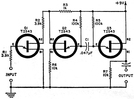
Fig. 1 - Monocycle multivibrator. A monocycle multivibrator may be defined as a multivibrator which is normally in a state where both of its transistors are off or non-actuated. Upon receipt of a pulse of proper polarity (in this case, positive) and sufficient amplitude, the circuit cycles once and turns off again. This is in contrast to a monostable multivibrator which, in its normal state, has one transistor conducting heavily, and upon receipt of a pulse, switches this transistor off and then on again. Current consumption of the monocycle multivibrator circuit given in Fig. 1 is less than 2 mA with a 9-volt power supply. In the circuit of Fig. 1, unijunction transistors Q2 and Q3 and associated components, make up the multivibrator proper. It will be noted that this part of the circuit is similar to that of the author's dual-UJT multivibrator (February 1969 issue), which is free-running, except that the 10,000-ohm load resistors have been transferred from the base-2 circuits to the base-1 circuits of the UJTs. This transfer keeps the circuit from firing of its own accord, but permits it to cycle once for each pulse received from UJT Q1. The signal from Q1 is introduced into Q2's base-2 circuit in a direction which causes Q2's base-2 potential to be pulsed downward. This allows Q2 to fire, and when its portion of the cycle is completed, Q3 fires, and the circuit returns to rest. UJT Q1 performs three functions: (1) It fires the monocycle circuit only when the amplitude of the input signal reaches a sufficiently high level; thus (2) it assures noise immunity; and (3) it provides a rectangular pulse to fire the multivibrator, even though the input signal may be of a sine or some other waveform. The circuit of Fig. 1 has been designed to handle repetition rates up to 120 pps. It fires dependably when a 3-volt r.m.s. sinewave signal or a 4.5-volt positive-going pulse is applied to the input terminals. A more sensitive circuit can be obtained by increasing the value of resistor R2 and decreasing the values of resistors R6 and R7. However, to do so reduces noise immunity. If R6 and R7 are made too low in value, the multivibrator may fire on power-supply noise pulses or break into oscillation as a free-running multivibrator. In the author's application of the circuit, a sharp positive-going spike was needed to actuate the following circuit. This was obtained by differentiating the output signal of the monocycle multivibrator and selecting the positive-going spike with a diode. The circuit isn't especially critical in respect to input-signal waveform. |
|||||||||||||
 |
|||||||||||||
|
|||||||||||||

|
||||||||||||||||||||||||||||||||||||


