|
|||||||||||||
 |
|||||||||||||
What Is a 300-Ohm Line?
|
|||||||||||||
In the mid- to late- 20th century, 300-ohm twin-lead cable served as the dominant transmission line for connecting television antennas to receivers. This Popular Electronics magazine article explains that the "300-ohm" rating represents the characteristic impedance of the line, which remains constant regardless of length when properly terminated. When matched at both the antenna and the TV, the cable functions as an "untuned" line, ensuring maximum signal transfer. If the termination does not match the cable's impedance, the line becomes "tuned," causing the input impedance to fluctuate wildly based on the cable's physical length - a property that can intentionally transform impedances at specific fractions of a wavelength. To maintain optimal reception and prevent signal degradation, the author stresses the importance of proper maintenance. Because outdoor connections are susceptible to weather, any necessary cable splices must be carefully staggered, soldered, and thoroughly insulated with plastic to ensure the integrity of the connection and prevent noise. What Is a 300-Ohm Line
We hear a great deal these days about characteristic impedance, which is also sometimes called iterative impedance or surge impedance. What is meant by characteristic impedance? When we speak of 300-ohm twin-lead for TV antennas, just what does the "300-ohm" refer to?
Measures 300 ohms (Z) at any frequency.
Measures 300 ohms (Z) at any frequency.
Measures very high (Z) at frequency f.
Measures nearly zero (Z) at frequency f.
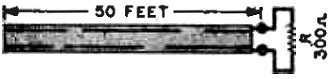
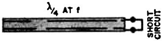
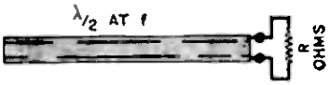
Measures R ohms (Z) at frequency f. The characteristic impedance of a transmission line is the impedance measured at the input of an infinitely long section of the line. Thus, if we measure the input impedance at some r.f. frequency of a 300-ohm twin-lead several miles long, it will be found to be approximately 300 ohms. If a short length of transmission line is terminated in an ,impedance equal to the characteristic impedance of the. line, the input impedance to the line will be equal to the characteristic impedance. The above statement is true regardless of frequency. For example, if we connect a 300-ohm resistor across the far end of a 300-ohm twin lead 50 feet long, and then measure the. impedance at the input, it will be found to be 300 ohms. This is true regardless of the frequency at which the impedance measurement was made. However, if the transmission line is terminated in some value other than its characteristic impedance, the input impedance may be widely different from the characteristic impedance, and its value depends greatly upon the length of the transmission line. If the transmission line is one quarter wavelength long, the results are most striking. In this case, the lower the terminating impedance, the higher the input impedance, and conversely, the higher the terminating impedance, the lower the input impedance.. As an extreme case, if the, far end, of a quarter wavelength line is short-circuited, the input impedance will be extremely high, infinitely high if the line itself was without loss. Or, if the far end of the quarter wavelength line was left an open circuit, the input impedance would be very low, zero ohms if the line itself was without loss. A line which is any odd multiple of a quarter wavelength (such as three-fourths wavelength) acts the same as a standard one-quarter wavelength line. When a transmission line is one-half wavelength long (or a multiple of one-half wavelength), the measured input impedance will always be equal to the terminating impedance. When the length of line is between one-quarter wavelength and one-half wavelength, its characteristics will be between those for a quarter wavelength and those for a half wavelength. Since the input impedance of a line terminated in its characteristic impedance is the same regardless of the length of the line, such a line is called an untuned transmission line. When a line is terminated in other than its characteristic impedance, the input impedance depends upon the length of the line, and is therefore called a tuned transmission line. In order to transfer the most energy from a source through a transmission line to a load, each end of the line should be terminated in a load which matches the line impedance. For example, to obtain a maximum signal into a TV set through a 300-ohm twin-lead-in, the line should be connected at one end to an antenna with 300 ohms impedance, and at the other end to a set with an input impedance of 300 ohms. As each end of the line is terminated in its characteristic impedance, we have an untuned line that can be any length.
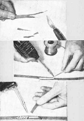
The 300-ohm twin-lead line interconnecting your TV set and antenna is an important link in the circuit. Many times in relocating the set in the house, you will need to splice two lengths of 300-ohm line. Special care must be taken in splicing lead-in outside the house, exposed to the weather. Uninsulated and carelessly made splices might generate noise and introduce line losses, especially in rainy weather. For this reason, it is essential that you know how to make a good splice. If you follow the photos below, your spliced line will be mechanically strong and durable, and as good as new electrically. - John A. Comstock First, cut one end of the 300-ohm line with one conductor about 1" longer than the other. Bare both conductors for about 1/2". Do the same to the other end to be spliced. Next, twist the bare leads together, the short lead of one end and the long lead of the other. Solder the splice with good resin core solder. Finally, insulate the splice using melted plastic from a scrap piece of tape, covering the splice as well as the spaces between it on both sides of the tape. |
|||||||||||||
 |
|||||||||||||
|
|||||||||||||



|
||||||||||||||||||||||||||||||||||||