|
|||||||||||||
 |
|||||||||||||
A 60-Cycle Repulsion Coil Resonance Engine
|
|||||||||||||
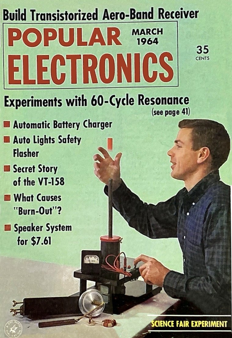
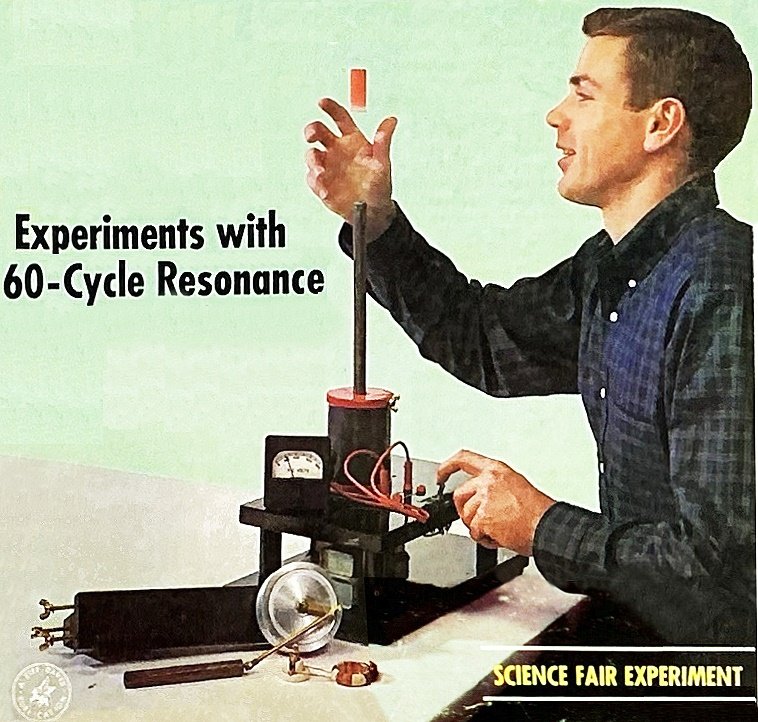
In the intriguing realm of low-frequency electronics, the device detailed in this 1964 Popular Electronics magazine article operates on 60-cycle household current. Its heart is a series-resonant LC circuit, where a custom-wound coil interacts with a precisely calculated 10.6 µf capacitor bank. The magnetic piston, a cylinder of bundled iron wire, is drawn into the coil when the circuit reaches resonance - the point where the coil's reactance equals the capacitor's. A flywheel and crankshaft assembly harnesses this force, carrying the piston past resonance to create continuous reciprocating motion, much like a miniature single-cylinder engine. Beyond the engine itself, the versatile unit enables several demonstrations of electromagnetic principles. It can function as a step-down transformer to light a bulb or, as a repulsion coil, launch an aluminum tube into the air due to opposing magnetic fields. The article meticulously guides the builder through fabricating every component, from the epoxy-glued iron core to the brass fittings, emphasizing safety with a discharge switch for the capacitors that can build over 400 volts at resonance. 60-Cycle Repulsion Coil Resonance Engine60-Cycle Repulsion Coil Resonance Engine
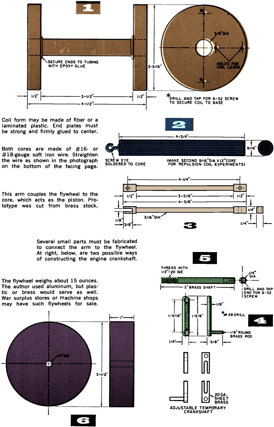
Startle your friends with this dynamic demonstration of low-frequency resonance and other dramatic a.c. effects. This Science Fair project works on ordinary 60-cycle house current. By Walter B. Ford Nearly every electronics experimenter is familiar with the process of adjusting a circuit to resonate at a specific radio frequency - you do this every time you tune in your favorite radio or TV station. Much more mysterious and surprising, however, are resonant circuits operating at the low 60-cycle frequency of our home lighting circuits. The repulsion coil-resonant engine described here reveals some of the secrets of this fascinating phase of electronics and provides a unit that can be used for a number of exciting experiments. The values and dimensions given here are from the author's working model, and while they may be varied, changes are not recommended unless the experimenter understands what effect the changes will have on the operation of the unit. If, for example, capacitors of lower value are used, the stroke of the engine piston will change. This will mean that there will have to he a proportionate change in the length of the flywheel crank. Making the Coil The inductive part of the series-resonant LC circuit used in the unit is in coil L1. Begin by making up a coil form as shown in Fig. 1 (page 43). Although plain wood discs may be used for the ends, plywood, fiber, or Micarta is preferred, since there is less chance of breakage if the coil is accidentally dropped. The center tubing can be Micarta, bakelite, or fiber, or can be made by drilling a 5/8" hole lengthwise in a piece of 3/4" dowel rod. Whichever material is used, make sure the inside surface is smooth, sanding if necessary, so the engine piston will travel freely.
Straighten the iron wire for the cores by stretching it as explained in text. Then cut and bundle the wires into cylindrical form as shown in Fig. 2. Complete the coil form by drilling holes in the end discs that make a snug fit around the center tubing, and gluing the ends and tubing together with epoxy glue. This step is important because there will be considerable pressure against the ends when the wire is in place on the coil. Drill 1/16" holes through one end of the coil form for the coil leads as indicated in Fig. 1. Drill and tap two holes for 6-32 machine screws in the same end of the form to hold the completed coil to its base (if wood is used, wood screws can be used and the threaded holes will not be needed) . Wind the coil form with 2-1/2 pounds of 24-gauge magnet wire. While it is not necessary to wind the coil perfectly, like thread on a spool, it should not be allowed to pile up at any one point.
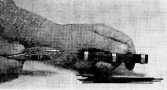
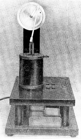
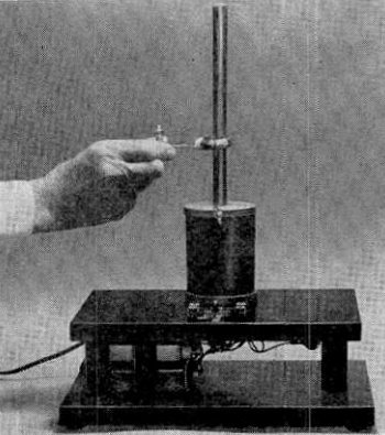
Constructed on a black lacquer wooden base, the resonant-coil engine is an impressive-looking unit. Constructing the Cores Uncoil enough 16- or 18-gauge soft iron wire to make the engine core, grip one end in a vise, grasp the opposite end with a pair of pliers, and pull until you can feel the wire stretch somewhat. This will straighten the wire. Cut the wire into 4-3/4" lengths and make forms to hold the bundle in cylinder form from pieces of thin -wall metal or plastic tubing. Holes (9/16") drilled in small pieces of wood or hardboard can also serve the purpose. Since the forms must be cut away after the core is glued, keep their outside dimensions down to a minimum.
Coil form may be made of fiber or a laminated plastic. End plates must be strong and firmly glued to center. Both cores are made of #16- or #18-gauge soft iron wire. Straighten the wire as shown in the photograph on the bottom of the facing page. This arm couples the flywheel to the core, which acts as the piston. Prototype was cut from brass stock. Several small parts must be fabricated to connect the arm to the flywheel. At right, below, are two possible ways of constructing the engine crankshaft. The flywheel weighs about 15 ounces. The author used aluminum, but plastic or brass would serve as well. War surplus stores or machine shops may have such flywheels for sale.
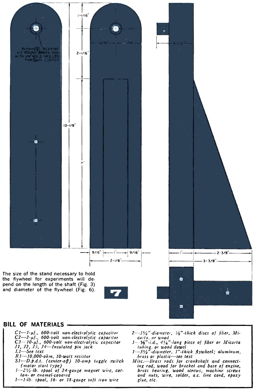
The size of the stand necessary to hold the flywheel for experiments will depend on the length of the shaft (Fig. 3) and diameter of the flywheel (Fig. 6).
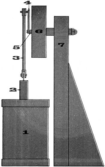
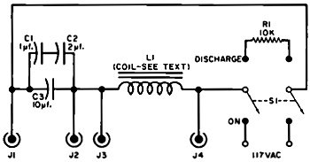
This is how the various pieces for the resonant engine shown in detail on page 43 are assembled. Bundle the 4-3/4" wires together and insert them in the forms. Press the end of a screw eye into the center of one end of the core, and cut off the ends of the wires forced out of the core at the opposite end. Withdraw the screw eye - it will be fastened permanently later. Apply epoxy glue to the areas of the core not covered by the forms holding the core wires and allow the glue to set. The type of epoxy glue that will set with artificial heat is preferred for this, since drying time is shortened and because surplus glue may be more easily pared off. After the glue has set, remove the forms and apply epoxy to the uncovered core areas. When this second application is dry, remove any rough spots on the core with a coarse file. Solder a screw eye in the hole that was made in the end of the core. The finished core should look like Fig. 2, on page 43. For the repulsion coil experiments, make another core following exactly the same procedure outlined, but using 12" iron wires and omitting the screw eye. Parts for the Engine The connecting rod (Fig. 3, page 43) is made with 3/16" brass tubing soldered into pieces of 1/4"-square brass, the ends of which have been drilled and shaped as shown. This construction was used to "dress up" the prototype, and need not be duplicated exactly. A rod made from a single solid piece of brass will work as well. The engine crankshaft is shown in two forms in Fig. 4. If you want to experiment with different values of capacitors, or longer or shorter piston travel with a corresponding change in speed, build the slotted version so you can adjust its length. The two parts are held together with a small machine screw and nut. Since this is made of lighter material, it is not recommended for permanent use. If all the values and measurements given for the engine are followed, make a solid crankshaft exactly like that shown. The engine flywheel is made of brass or aluminum, and is 1" thick and 3-1/4" in diameter. It is supported by a 1/4" brass shaft 3" long (see Figs. 5 and 6, page 43) . Although the weight of the flywheel should not be too critical, some experimenting may be in order. The author's was made of aluminum and weighed one pound. Drill and tap one end of the flywheel shaft for a 6-32 machine screw and thread the opposite end with a 1/4"-20 die. The flywheel shaft bearing - a 1-1/2" brass rod 1/2" in diameter with a 1/4" hole drilled through the center-is mounted in the bracket shown in Fig. 7 and in the assembly drawing. The bracket is made with a stiffening buttress so that it will stand up under the vibration of the engine. In the author's unit, the bracket was mounted to the coil platform by tapping three small pieces of brass rod and cementing them into holes drilled into the bottom of the bracket. Wing bolts thread into the holes from the bottom of the coil platform, making it easy to disassemble the engine for other experiments. In any case, drill a 1/2" hole in the bracket at the height shown in Fig. 7, and cement the bearing in it with epoxy glue. Mounting Stand Make a double-deck stand as shown in the photos and secure the capacitors, C1, C2, C3, to the lower section. Mount the d.p.d.t. toggle switch, S1, and four pin jacks, J1, J2, J3, J4, on the upper deck of the stand in front of the coil position. Drill holes in the upper deck for coil leads, coil mounting screws, bracket mounting screws, and for the engine piston. The piston hole should be large enough to provide ample clearance. Mount all of the parts on the stand as shown in the assembly view on page 45. Solder the end of the flywheel shaft to the end of the crankshaft where the two join together. To hold the long 12" core in place for repulsion coil experiments, drill and tap the top disc for a setscrew that extends from the outer rim into the center hole. Connect the parts as shown in the schematic diagram on page 45. You will note that the diagram shows a "discharge" position for S1. This is a safety device to discharge the capacitors after the unit has been in use. Label S1's positions (S1 is a center-off type) "On," "Off," and "Discharge." Testing the Engine When the assembly and wiring are done, spin the flywheel by hand to make certain there is no undue friction. Use light oil on all bearings and piston surface. With everything ready to go, plug the unit in, turn the switch on, and give the flywheel a turn in either direction. The flywheel will pick up speed and be on its way. Like most single-cylinder reciprocating engines - your engine will require an initial start, unless the crank is turned to its upper position and slightly off center. Theory How does the resonant engine operate? One of the laws governing a series-resonant circuit is that when the reactance of the capacitor equals the reactance of the coil, the maximum amount of current will flow in the circuit. The reactance of the capacitors is fixed; the reactance of the coil depends on the piston core's position. When the piston core is slightly above its lowest point of travel, or the same distance below its upper point of travel, the reactance of the coil equals that of the capacitor, and the circuit is resonant. In operation, the piston is drawn toward one of the resonant positions, but the flywheel carries it beyond that point and the circuit drops sharply out of resonance. From there on, the piston is carried by the momentum of the flywheel to the next resonant position. The value of the capacitance needed for the resonant engine is 10.6 µf. As shown in the schematic, the author got this value by connecting 1- and 2-µf. units in series, and then connecting them in parallel with a 10-µf. unit. Other combinations can, of course, be used to arrive at 10.6 µf. Other Experiments
A small coil connected to a flashlight bulb illustrates transformer action of mutual inductance.
Permissible changes in certain component values are discussed in text. However, do not eliminate discharge function of the d.p.d.t. toggle switch. Want to make a step-down transformer? Wind a 40-turn coil of wire and connect it to a flashlight bulb. Position the long core in the engine coil, tighten the setscrew, and slowly bring the flashlight bulb and coil down over the core. An interesting variation is to try the same thing with the capacitor shorted out by means of a jumper across the two capacitor pin jacks. The increased brilliancy of the bulb with the capacitor in the circuit shows how much more efficiently a.c. circuits operate at resonance. Another intriguing experiment using the transformer principle is the repulsion coil. Secure a piece of 5/8"-i.d. aluminum tubing 2" long. Place the tubing over the long core, turn the switch on, and it will shoot skyward. Adjust the center core to get maximum upward thrust if necessary. The transformer principle involved here is that of mutual induction where a varying current flowing in a coil induces a current in another coil placed in the same magnetic field, such as the primary and secondary of a transformer. The induced current is always in an opposite direction to the original current; thus, the magnetic fields set up by the two currents will be in opposition. The aluminum tubing acts like the secondary of a transformer, and, since it is free to move, opposing magnetic fields send it flying. A similar piece of aluminum tubing 3" long can be made to oscillate up and down the center core for approximately 8" by adjusting the core to proper height. The height is critical - 1/16" either way may prevent the tubing from oscillating. If you have an a.c. voltmeter with a maximum range of at least 500 volts, it can reveal some startling facts about series resonant circuits. Connect the meter to J3-J4 across the coil and adjust the long center core until the meter gives a maximum reading. Change the voltmeter to the capacitor jacks J1-J2 and note the reading. Readjust the center core until the coil and capacitor voltmeter readings are the same. The circuit is now at resonance, and the voltage indicated across each unit should be about 400 volts. In a series resonant circuit such as this, the maximum current will flow at resonance. At 60 cycles, the reactance of the capacitor bank comes to about 250 ohms; and at resonance, the reactance of the coil will also be 250 ohms. However, at resonance, these reactances cancel one another-the current flow is limited only by the small resistance in the circuit. It is this current flow in combination with the reactances of the coil and capacitor - which may be said to build up the voltage by "handing it back and forth" - that accounts for the exceptionally high counter electromotive voltages. The experiments and demonstrations suggested above are just a few of those that can be performed with the unit. As you become familiar with it, many more will suggest themselves to provide further exploration of this intriguing phase of electronics. |
|||||||||||||
 |
|||||||||||||
|
|||||||||||||

|
||||||||||||||||||||||||||||||||||||


