|
|||||||||||||
 |
|||||||||||||
Among the Novice Hams
|
|||||||||||||
As with on my Airplane and Rockets hobby website, a big part of my motivation for scanning and posting these vintage electronics magazine articles has been two-fold. The primary purpose is to provide access to historical documents for research and educational reasons. The second reason is to have the names of people and places published in text format (everything OCRed) so that someone doing a Web search for himself, a relative, or a friend, might run across it here. I receive e-mails occasionally from readers who are thrilled to find those names in an old article, especially when the person discovered has passed on and it serves as a fond remembrance. Features such as this Among Novice Hams - a regular column in Popular Electronics magazine of the era - is a great place for finding them. Among the Novice Hams
In October we discussed some of the fundamental properties of current, voltage, and resistance, and how the relationship between them is expressed concisely by ohm's law: E = IR, I = E/R, R = E/I. We also talked about the formulas for calculating the power in electrical circuits, P = EI and P = I2R, and how to use them answering simple questions involving ohm's law and power calculation that may found in the Novice examination. Now, we'll go over the information necessary to understand and answer questions that might appear in the General/Technician/Conditional exam.
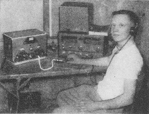
Fred Beyer. KN9HFP, made 200 contacts in 35 states in five months as a Novice. His transmitter is a DX·20 feeding a dipole; His receiver is an NC-98.
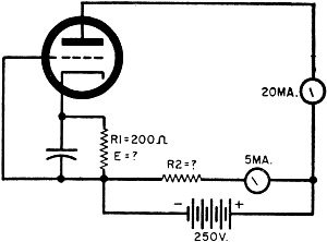
Fig. 1 - This diagram, with different component values, is the basis for several questions on ohm's law which appear in the General Class Amateur exam.
Ken Grimm, KN5KBH, works 16-meter c.w. with a DX-100 transmitter cranked down to 75 watts at Baylor University Radio Club. In the General Class examination, there are usually a couple of questions based on the diagram in Fig. 1, such as: "What is thee bias voltage on the tube?" And: "What is the resistance of R2?" It is important to read each question separately and then study the diagram to determine which of the data given is pertinent to that question. Once this is done, the problem is half solved. For example, there is nothing difficult about determining the resistance of R2. From ohm's law, R = E/I; therefore, you simply divide the voltage across R2 by the current flowing through it. Both of these quantities are given. Remembering to change milliamperes to amperes, the solution will be: R2 = 250/0.005 = 50,000 ohms. What It's All About "Among the Novice Hams" is devoted to the beginning radio amateur. If you are familiar with amateur radio, it speaks for itself. If not, the following may help you understand what it s all about. Amateur radio is a hobby in which a quarter million people throughout the world, from grade school boys and girls to men and women, operate their own officially licensed radio stations. They communicate with each other over distances ranging from a few miles to 12,000 miles. The simplest amateur license to obtain is the novice license. It is issued by the Federal Communications Commission, Washington, D.C., to any citizen who has not previously held an amateur license and who can send and receive the International Morse code at a speed of five words a minute - actually a very slow speed. In addition, it is necessary to pass a simple written examination on elementary amateur radio theory and regulations. The license is valid for one year, during which time the licensee must qualify for a permanent license or leave the air. Full information on how to obtain the various classes of amateur licenses may be found in a packet of booklets called "Gateway To Amateur Radio." The booklets are available for $1.50, postpaid, from the American Radio Relay League, Inc., West Hartford, Conn., or from any of the amateur supply houses that advertise each month in Popular Electronics. Read "Among The Novice Hams" for up-to-date news and discussions of interest to all beginning amateurs. The bias voltage on a tube is the fixed voltage applied to its control grid with reference to its cathode. In this circuit, the voltage across the cathode resistor R1 establishes the bias voltage. The problem, therefore, is to determine what this voltage is. From ohm's law, E = IR1. R1 is given as 200 ohms. I is the 20-ma. plate current of the tube, which flows from the negative battery terminal, through R1, through the tube, and back to the positive battery terminal through the milliammeter. Thus, E = IR1 = 0.02 x 200 = 4 volts. The bias voltage is 4 volts. Resistance in Series. Figure 2(A) shows three resistances connected in series. From it, it is obvious that for an electric current to travel from one end of the string to the other, it must flow through each resistance in turn; therefore, the total resistance must be the sum of the individual resistances, or Rtotal = R1 + R2 + R3, etc. For the values shown, the total resistance is 1000 ohms. Resistances connected in series across a voltage source are usually called voltage dividers because, by proper choice of the individual resistances, any desired percentage of the total voltage can be obtained at the taps between them. A voltage divider is often used across the output terminals of a power supply; there it serves the dual purpose of keeping a minimum load on the supply and furnishing intermediate voltages to the associated equipment. For practice, let's design a voltage divider to do a specific job. Assume that we have a transmitter requiring 500 volts at 100 milliamperes (0.1 ampere) for the final amplifier tube plate circuit, and 250 volts at 50 ma. (0.05 amp.) and 100 volts at 10 ma. (0.01 amp.) at other points. A power supply capable of delivering 500 volts at a maximum of 200 ma. is available. Referring to Fig. 2(B), the first step in calculating the resistances in the voltage divider is to decide on how much "bleeder current" to allow to flow through it. Normally, about 10% of the current capacity of the power supply is allocated for the purpose. Ten percent of 200 ma. is 20 ma. When added to the 160 ma. drawn by the transmitter, this makes the total key-down current drain on the supply 180 ma.
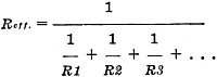
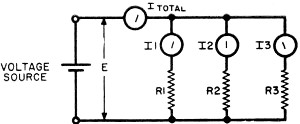
Fig. 2 - How resistances connected in series (A) can be used as a voltage divider (B) to deliver several voltages from a single power supply (see text). Starting at the bottom of the divider, the only current that flows through R1 is the bleeder current, while the voltage across it is obviously 100 volts. Substituting these values in the appropriate ohm's law formula gives: R1 = 100/0.020 = 5000 ohms. Proceeding to R2, the current through it is the 20-ma. bleeder current, plus the 10 ma. drawn from the 100-volt tap, or 30 ma. The voltage across it is the difference between the voltages at the two taps: 250 volts-100 volts = 150 volts. Solving for the resistance of R2 using these values gives: R2 = 150/0.030 = 5000 ohms. To calculate the value of R3, we add the 50 ma. drawn from the 250-volt tap to the 30 ma. already accounted for, making the current through it 80 ma. The voltage across it is 250 volts (500 volts - 250 volts). Solving ohm's law with these values gives: R3 = 250/0.08 = 3125 ohms. Then add the three resistance values together: 5000 + 5000 + 3125 = 13,125 ohms. One large resistor (13,000 ohms would be close enough in an actual circuit) with adjustable taps or three separate resistors could be used. To complete the calculations, determine the current that will flow through the divider with no connection to the taps by dividing the supply voltage by the resistance: I = 500/13,125 = 38 + ma. Because the supply voltage will undoubtedly in-crease somewhat under no-load conditions, the actual current will probably be at least 40 ma. This is more current than flows through R1 and R2 when power is being delivered to the transmitter; therefore, R1 and R2 must be large enough to carry this current without overheating. Use either of the power formulas to determine the wattage rating of the resistors. Under no-load conditions, the voltage at the divider taps will be higher than when they are under load. The main advantage of a voltage divider over series dropping resistors is that voltage variation between the load and no-load conditions is minimized. Resistances in Parallel. Figure 3 shows three resistances in parallel. The formula for calculating the effective resistance of such a combination is:
If you are a whiz at algebra, you know exactly how to solve this formula and need not worry that you may be asked about it in the examination. If not, you will probably say: "Fine, but what does it mean?" Fortunately, it's easy to understand with a bit of explanation.
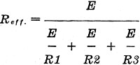
Fig. 3 - How to calculate the effective resistance when three resistances are connected in parallel. Referring to Fig. 3 and taking each resistance in turn, we know from ohm's law that the currents through them are: I1 = E/R1, I2 = E/R2, and I3 = E/R3. Furthermore, the total current is the sum of the individual currents: Itotal = I1 + I2 + I3, or Itotal = E/R1 + E/R2 + E/R3. Reverting to the fundamental ohm's law again, the effective resistance of the three resistances in parallel is:
Of course, we can make E any value we wish, as long as it is the same in each part of the equation. For convenience, E is usually made equal to one volt in parallel-resistance calculations, making the last equation the same as the first one given here. The effective resistance of 2-, 4-, and 5-ohm resistors in parallel is 1.05 (to two decimal places). I suggest you verify this answer for practice and then make up a few practice problems of your own. In checking your answers, remember that the effective resistance is always less than that of any of the individual resistances.
Posted April 26, 2021 |
|||||||||||||
 |
|||||||||||||
|
|||||||||||||


|
||||||||||||||||||||||||||||||||||||


