|
|||||||||||||
 |
|||||||||||||
Easy-to-Build Beam Antenna
|
|||||||||||||
I wonder whether Mr. Jim Fahenstock, author of this 1960 Popular Electronics magazine article titled "Easy-to-Build Beam Antennas," was related to Archer Pleasant Fahnestock, president of the Fahnestock Electric Company, maker of the famous Fahnestock Clips? A Web search turns up plenty of Fahenstocks all over the country now (including some convicted criminals!), but how many could there have been in 1960 - sort of like with Blattenbergers - nearly all in the Buffalo, New York region. But I digress... This article highlights the growing necessity of beam antennas for amateur radio operators facing increasing spectrum congestion. By utilizing readily available hardware store aluminum, hobbyists can construct a cost-effective 15-meter beam antenna to significantly improve performance. The construction guide details the assembly of a boom, driven element, and director using telescoped tubing and custom-made shims for a secure fit. A gamma matching section, paired with a variable capacitor for impedance matching to 52-ohm coaxial cable, is recommended to minimize the standing-wave ratio. The author emphasizes that beyond technical advantages, the beam improves an operator's morale and success rate in making contacts, offering a practical path for hams to upgrade their stations through DIY craftsmanship.
Easy-to-Build Beam Antenna
Pull in the DX and cut down noise and interference. By Jim Fahenstock, W2RQA Beam antennas are becoming increasingly popular among users of frequencies above 14 megacycles. While once considered a luxury in amateur radio circles, the beam is rapidly joining the list of necessities as the spectrum becomes more crowded and competition more severe. - Thanks to "do-it-yourself" aluminum, which can be found in almost any hardware store, a ham or short-wave listener can start on a beam for a small investment of tubing and brackets. To squeeze out every possible ounce of performance, let's sacrifice multi-band operation and pick 15 meters, meeting place for veterans and Novices alike. The dimensions shown in Fig. 1 were chosen for approximately the middle of the c.w. portion of the 15 -meter band (21.2 mc.). These dimensions are not extremely critical. For other frequencies, the proper lengths can be calculated using the simple formulas: Driven element (in feet) = 475 / freq. (mc.) Director (in feet) = 455 / freq. (mc.)
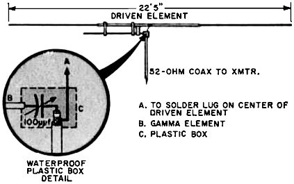
Fig. 1 - Shield of 52 -ohm line iv connected to driven element and inner conductor to gamma element via the variable capacitor. To eliminate the box, use a weatherproofed fixed capacitor of optimum value.
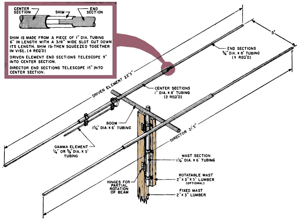
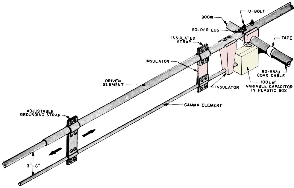
Fig. 2 - Beam dimensions shown are for the 15-meter band. You can ''cut" the beam for other bands by using formulas given in text. The gamma matching bar is a proportionate length. Construction The boom is a 6' length of 1¼" tubing. (See Fig. 2). The two center element sections are 8' lengths of 1" tubing and the four end element sections are 8' lengths of 3/4" tubing telescoped into -the center elements. A 1¼" x 6'. length of tubing serves as a mast. You can substitute a length of 2"x3" lumber for the mast in the initial installation if you wish. To create a snug fit at the telescope joints, the following procedure is recommended. Take a 6" length of 1" tubing and, with a hacksaw, cut a 3/8" slice along the length of the tube. Then, squeezing the slotted' section in a vise, reform the tube by closing the slot. This will create a new piece whose outside diameter corresponds roughly to the inside diameter of the 1" tubing, and whose inside diameter approximates the 3/4" tubing's outside diameter. After you prepare four such shims, and insert them into the ends of the 8'sections of 1" tubing, then insert the 8' sections of 3/4" tubing into the shims. For the radiator, or driven element, the overlap will be 9", and for the shorter director, the overlap will be 15". The 3/4" end sections can be held firmly in place by several sheet metal screws which are long enough to pass through both pieces of tubing and the shim as well. When the driven element has been assembled, the gamma matching section is attached to it. To form the gamma matching section mounting straps, bend the ends of a 6" strip around the 1" tubing and the gamma matching bar, and drill holes for screws and nuts to clamp the tubing. You can make the gamma matching bar from five feet of 1/4" or 3/8" tubing. The strap on the inner end must be insulated from the driven element, and the insulation must be strong enough to withstand anticipated strain due to wind - its electrical properties are not too critical. The insulated waterproof box housing the receiving-type 100-µµf. variable capacitor can be attached to the boom or the driven element. Note that the outer conductor of the coax must be connected to the center of the driven element so that the exact location of the box depends on its size. A fixed capacitor could be used instead, and its value determined by experiment; this would eliminate need for the box. Assemble the antenna by laying the two completed elements on the ground and attaching the boom using standard hardware intended for holding TV antennas to their masts. Separation of the driven element and the director is not too critical - with the full 6' length as the boom, the elements can be placed 4" to 6" from either end. Movement of the elements after installation affords a degree of adjustment to improve front-to-back ratio using a remote signal strength indicator. Connect the center of the boom, by means of another TV clamp, to a mast of 1!4" tubing. In lieu of a mast, a vertical 2" x 3" may be used with a 1¼" pipe strap to hold the boom. By connecting this "mast" to another 2"x3" with heavy hinges, the array can be rotated almost 180° at minimum cost. The beam and its aluminum mast are so light that, they can be supported in a fixed position using a small' vise to hold the mast to some permanent part of the house or other structure. Adjustment The gamma matching section presents the correct impedance for standard five-cent-per foot 52-ohm coaxial cable (RG-58/U). In adjusting the dimensions of the gamma matching section, there is no substitute for a standing-wave-ratio bridge or reflected power indicator. Both the matching section and the value of the capacitor should be adjusted to minimize SWR. You'll find that the gain of the antenna will theoretically be only unity, but signals arriving at the ends will definitely be weaker than , those arriving broadside. Later, if you wish, you can add a third element - a reflector - for increased gain. You'll find that the gain of the antenna will theoretically be only unity, but signals arriving at the ends will definitely be weaker than those arriving broadside. Later, if you wish, you can add a third element - a reflector - for increased gain. Aside from adding to the signal strength of a station, a beam adds to the morale and courage of its user. The rare ones become more common. Disappointments in multiple layer pile-ups are rare, and 100% QSO's are the rule rather than the exception. |
|||||||||||||
 |
|||||||||||||
|
|||||||||||||

|
||||||||||||||||||||||||||||||||||||


