|
April 1974 Popular Electronics
 Table of Contents Table of Contents
Wax nostalgic about and learn from the history of early electronics. See articles
from
Popular Electronics,
published October 1954 - April 1985. All copyrights are hereby acknowledged.
|
A major transition in the
realm of test equipment readouts from analog to digital was occurring during the
1970s. Prior to then, what few digital displays existed used Nixie tubes, but the
emergence of inexpensive LEDs, combined with equally inexpensive digital logic ICs,
made the change an easy decision. D'Arsonval meter movements are prone to damage
when even slightly overdriven or subject to physical impact. Analog meter movements
still have their place in a few applications (like when a quick at-a-glance,
pert-near reading is good enough, particularly with slow, continuous
level changes), but the precision and repeatability of digital circuitry, plus lack
of subjective interpretation of a pointer's position makes it the option of choice
most of the time. This 1974 Popular Electronics magazine "How to Make Custom
Meters from Salvaged Parts" article might have been in a WWII era script from when
new electronics parts were hard to find since everything was
going toward
the war effort. Unbeknownst to readers, within two decades shiploads of cheap,
readily available components of every imaginable form, fit, and function would be
flowing in from China and other Communist, dictatorial countries where people build
them under miserable conditions and at barely survivable wages. I have to comment
on Fig. 4 showing a carbon resistor being filed to adjust its value. That's
fine, but a protective sealant needs to applied to prevent oxidation and/or contamination
which will, over time, change the resistance.
How to Make Custom Meters from Salvaged Parts
Surplus D'Arsonval movements are easily converted to special-purpose voltmeters
and ammeters
By Prof. Robert Koval

Fig. 1 - The first step is to disassemble and clean the
surplus meter.

Fig. 2 - Use this setup (with VOM and 1.5·V cell) to check
movement's full-scale value.

Fig. 3 - Simple circuits for determining the resistance
of the original meter movement.
With the switch to digital logic and numeric readout devices in modern test equipment,
the surplus market is becoming glutted with D'Arsonval meter movements. Actually,
the availability of these parts is a boon to the electronics experimenter because
the going prices for the movements are often only a small fraction of what he would
have to pay if purchased from an industrial supply house.
Most surplus meter movements can be refurbished and custom designed to suit just
about any metering need imaginable. The process is relatively simple.
Preliminary Steps. Because the meter movement is from a surplus parts store,
the first task is to clean away all dirt and other foreign matter from the case.
This can be done with warm water and soap. For tough, greasy build-ups, try using
some rubbing alcohol.
Once cleaned, carefully disassemble the movement (Fig. 1). Then inspect
the movement to determine whether or not any resistors have been installed. Since
you need only the basic movement for the next step, any resistors you find can be
discarded.
Now, get out your VOM, a 2-megohm potentiometer, and a 1.5-volt dry cell with
holder. Wire up the circuit shown in Fig. 2, but do not install the battery
in its holder until after you adjust the pot for maximum resistance. Connect the
battery and slowly adjust the setting of the pot to obtain exactly full-scale pointer
deflection on the meter movement. (Note: Temporarily replace the old meter scale
to locate the full-scale position.) Since the meter under test is in series with
the VOM, both units carry the same magnitude of current. Hence, the VOM's reading
is the full-scale current sensitivity of the meter movement.
At this point, the resistance of the meter movement (Rm) must be determined.
Do not use an ohmmeter to measure the movement's resistance; the current supplied
by the ohmmeter could easily damage the movement beyond repair. A method has been
developed for calculating Rm using only the basic movement, two resistors of known
value, and a 1.5-volt dry cell. The circuit hookup is shown in Fig. 3. Series
resistor Rser should have a value large enough to permit I1 to fall within the upper
third of the scale. As a guide for choosing Rser, use Ohm's law. Assume the dry
cell to be delivering 1.5 volts, and work this against the basic movement's full-scale
current sensitivity. A fixed precision resistor would be ideal for Rser. The value
of Rsh should be 1/10 or 1/20 the value of Rser. You can determine I1 and I2 from
the meter's scales. Calculate Rm as follows:

You now have enough information to custom-design a voltmeter or ammeter.
 The Custom Voltmeter. It is usually convenient
to customize a meter movement in such a manner that it retains the same numeric
sequence on the original meter scales to obviate the necessity of relabeling the
scales. However, this is not absolutely necessary if you do not mind the task of
removing the old and applying new legends. The Custom Voltmeter. It is usually convenient
to customize a meter movement in such a manner that it retains the same numeric
sequence on the original meter scales to obviate the necessity of relabeling the
scales. However, this is not absolutely necessary if you do not mind the task of
removing the old and applying new legends.
Since the meter movement shown in Fig. 1 has a numeral 50 at its full-scale
index, let us design a voltmeter with a 0-5-volt range. Assume that 50 μA is
needed to deflect the pointer to full scale and that Rm is 2090 ohms. To calculate
the value of the multiplier resistor (Rmult) for any given voltage range (Vr), use
the following equation:
Bmult = (Vr X 1/Im) - Rm
In the equation, Rm is the basic movement's resistance (2090 ohms in our example),
Vr is the voltage range desired (0-5 V full-scale), and 1/Im is the reciprocal of
the current needed to obtain full-scale pointer deflection (1/0.000050). Hence,
Rmult = (5 X 1/0.00005) - 2090 = 97,910 ohms.
As illustrated in the above example, a 97,910-ohm resistor will yield a 0-5-volt
range when connected in series with the basic meter movement. To change ranges,
simply substitute the desired full-scale figure for Vr in the equation. If you want
multi-range capability, calculate Rmult for each range desired and use a rotary
switch for range selection.

Fig. 4 - The resistance of an ordinary carbon resistor can
be trimmed by using a file.

Fig. 5 - The basic setup to be used for determining shunt
resistor for an ammeter.

Fig. 6 - A hand-wound shunt resistor. Next the assembly
is protected with a coil dope.
Very likely, the value calculated for Rmult will not be readily available from
the commercial selections listed. Do not let this deter you. It is a simple matter
to arrange two or more resistors in series/parallel hookups to yield the required
ohmic value. Alternatively, you can "trim" an ordinary carbon resistor to the proper
resistance with the aid of a file (see Fig. 4). Select a fixed resistor of
slightly lower value than required. For example, if you need 97,910 ohms, a standard
91,000-ohm carbon resistor can be used. Use an ohmmeter to verify that it is indeed
less than 97,910 ohms; a 10-percent tolerance resistor can go as high as 100,100
ohms, a useless figure for the trimming procedure.
Use a resistance bridge or an ohmmeter to monitor your progress as you cut into
the resistor with the corner of a triangular file. Work very carefully so as not
to trim away too much of the composition resistance material and end up with a value
too high for your needs. When the resistor is trimmed to the proper value, liberally
coat the notch with coil dope to seal out moisture. This will assure a constant
resistance under changing humidity conditions.
The multiplier resistor can be mounted inside or outside the meter's case. A
tag indicating the range and units can then be affixed to the meter face. Make it
large enough to completely cover the original legend.
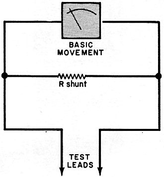
The Custom Ammeter. A custom ammeter can be designed around the basic meter movement
with much the same ease encountered when making the voltmeter. The
basic hookup is shown in Fig. 5. The equation to use for determining the
resistance of the shunt resistor is:

Maximum current Imax is the desired full-scale current the meter is to indicate;
Im is the current required to deflect the meter's pointer to full-scale; and Rm
is the resistance of the basic movement.
Assume that you want a range of 0-50 mA and that Rm and Im remain the same as
in the voltmeter example given above. Then, Rshunt would be equal to (2090 X 0.00005)
/ (0.05 - 0.00005), or 2.092 ohms. Again, if a different range or ranges are desired,
the maximum current wanted would be inserted into the equation as Imax. A switching
arrangement would be used to provide several ranges.
The value of Rshunt will normally be very low, sometimes on the order of only
a fraction of an ohm. In cases where its value would be too low to be conveniently
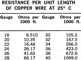
trimmed with a file, you will have to wind your own shunt resistors. Enamel-coated
copper wire can be used as the resistive element, while the resistor form can be
any high-value resistor (1 megohm will do). Wire gauges and the resistance they
yield are given in the Table. A hand-wound shunt resistor assembly is shown in Fig. 6.
After winding the wire onto the resistor body and soldering the wire's ends to the
resistor's leads, coat the assembly with coil dope.
As with the voltmeter, the ammeter's shunt resistor can be mounted inside or
outside of the meter's case. Also, be sure to label the meter face with the range
and unit for which it is designed. To check out your ammeter, connect it in series
with a VOM and current source; both meters should dictate the same magnitude of
current.
Posted February 1, 2024
(updated from original
post on 3/27/2017)
|


 The Custom Voltmeter. It is usually convenient
to customize a meter movement in such a manner that it retains the same numeric
sequence on the original meter scales to obviate the necessity of relabeling the
scales. However, this is not absolutely necessary if you do not mind the task of
removing the old and applying new legends.


