|
|||||||||||||
 |
|||||||||||||
Kill Those Harmonics
|
|||||||||||||
Here is a short tutorial on how to construct a ¼-wave stub "trap," or filter to attenuate even-order harmonics from transmission lines. It applies whether the transmission line is feeding an antenna or is a section of copper foil running on a microwave substrate. Author Kent Mitchell (W3WTO) discusses both an open stub and a shorted stub. In case you are not familiar with how quarter-wave transmission lines stub work, a short at the far end appears as an open circuit where the stub connects to the main transmission line, and an open stub line appears as a short circuit. That is because there is a 180° phase shift at the end of the shorted stub and a 0° phase shift at the end of the open stub. Therefore, there is a total of 360° (i.e., 90°+180°+90°=360°, equivalent to 0°) with the shorted ¼-wave stub so it has no effect where it attaches to the main transmission line. The open stub experiences no phase shift at the open end, so there is a 180° phase shift (90°+0°+90°=180°) seen at the main line attachment point. The moral of the story is that if you make the open stub equal in length to ¼ of the wavelength (in the cable, while accounting for velocity factor) of the interfering signal, it effectively gets shorted out. This article appeared in a 1960 edition of Popular Electronics magazine. Kill Those Harmonics
Fig. 1. - Quarter-wave stub filters can be of either the "shorted end" (A) or "open end" (B) types. Both types eliminate even-order harmonics.
Fig. 2. - T-connector inserted in coaxial transmission line makes convenient jack for connecting shorted-stub filter.
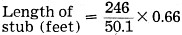
Fig. 3. - Open-stub filter can be soldered directly into transmission line using open-wire or twin-lead construction. Inexpensive, easy-to-make tuned stubs will eliminate harmonics from your CB or ham rig Whether you're a Citizens Bander or a ham operator, harmonics from your transmitter can ruin your neighbor's TV pleasures and bring him pounding on your door. Likewise, the FCC takes a dim view of anyone who clutters up the bands with spurious radiations. One sure way to help clean up your signal is to connect a stub filter to your antenna transmission line. Although relatively simple and inexpensive, quarter-wave stub filters are very effective in eliminating even-order harmonics (2nd, 4th, 6th, etc.) from the output of a transmitter feeding a single-band antenna. There are two types of quarter-wave stub filters. In one case, a quarter-wave stub with a shorted end is connected in parallel with the transmission line; in the other, a quarter-wave stub with an open end is hooked up in series with either leg of the transmission line. Let's see how these two types of stubs work and how they are used. Figure 1 (A) shows a shorted quarter-wave stub connected in parallel with the transmission line from transmitter to antenna. Since the stub is a quarter wavelength of the signal frequency, it presents a very high impedance to the transmitted signal, and the signal passes on to the antenna with little or no loss in power. Even-order harmonics, however, are confronted with a virtual short circuit, since the stub offers a very low impedance at these frequencies. The parallel shorted stub is easily connected to coaxial transmission lines as well as twin-lead and open-wire lines. Figure 1(B) shows an open-end quarter-wave stub hooked up in series with the transmission line. The stub offers little or no resistance to the fundamental fre-quency, allowing it to pass to the antenna. Even harmonics, on the other hand, "see" some multiple of one-half wavelength - a near-infinite impedance for these frequencies-which prevents them from reaching the antenna. Open-end series stubs are not suitable for coaxial transmission lines since they are difficult to connect to this type of line. However, connection to either a twin-lead or open line is simple. To make a stub filter for your ham or Citizens Band transmitter, use a piece of transmission line of the same type and impedance you presently use. To determine the length of the stub, substitute the fundamental frequency of your transmitter in the following formula: Incidentally, coaxial cables such as RG-8/U, RG-58/U, RG-11/U, and RG-59/U have a velocity factor of 0.66; flat 300-ohm TV twin-lead has a velocity factor of 0.82; tubular 300-ohm line is rated at 0.84; and the popular 450-ohm open-wire transmission line at 0.90. As an example, let's say we are going to cut a shorted stub filter for the 6-meter amateur band on 50.1 mc., using coaxial cable. Applying the formula, we find: = 3.24' or 39" A quarter-wave shorted stub for the popular CB channel 11 (27.085 mc.) would be determined as follows: Hook up the stub to your coax transmission line using aT-connector (Amphenol 82-36 or equivalent) as in Fig. 2. Then Hook up the stub to your coax transmission line using a T-connector (Amphenol 82-36 or equivalent) as in Fig. 2. Then just attach a male coax connector (Amphenol 83-851 or equivalent) to the stub so that it can be easily connected to the T-connector. For twin-lead or open-wire stubs, solder the stub directly to the line as shown in Fig. 3. Keep in mind that a stub filter is not intended to replace a low-pass filter but rather to supplement one. A stub filter is more efficient in attenuating troublesome even harmonics which can be a cause of TVI, while a low-pass filter attenuates all harmonics very effectively.
Posted August 24, 2020 |
|||||||||||||
 |
|||||||||||||
|
|||||||||||||


|
||||||||||||||||||||||||||||||||||||


