|
|||||||||||||
 |
|||||||||||||
After Class: The Load Line Story
|
|||||||||||||
If you are familiar with Saunder Harris' "After Class" stories for Popular Electronics magazine, you know they were written in the form of a story that describes a mentor mentoring a mentee (yes, mentee is a real word). "The Load Line Story" presents a quick lesson on how to determine the operational points of in this case a vacuum tube, but it applies equally well to a transistor. If you have had a difficult time conceptualizing the usefulness of I-V curves a load line, then this might be just what you need to get you going. Sure, all the designers out there do this in their sleep, but remember that every day there are new people getting into electronics and this is what they are looking for to help get them on the path to where you are. After Class: The Load Line Story By Saunder Harris
Load lines are as fundamental to vacuum tubes as vectors are to mathematics - here's what they're all about. Larry was sitting at Ken's workbench watching him fill out QSL cards for the afternoon's hamming contacts. "Do you have tine for a bit of explaining, Ken?" Larry asked his older friend. "We were, discussing load lines at the school radio club 'today and none of us really understood much about them. I told the fellows that you'd set me straight and I'd pass the dope along to them." Ken pushed the cards aside and checked his watch. Sue, Larry, I'll be glad to throw some light on the load-line situation. Actually, it isn't a complicated subject - if you know Ohm's law and a few basic facts about working of tubes." Larry laughed, "I know about Mr. Ohm all right; but. at times what you call basic looks mighty un-basic through my specs. If you're willing, though, I'd sure appreciate it." Ken was very assuring. "I guarantee these will be basic basics." He handed Larry a small book. "Here, glance through this while I do a little circuit drawing. It's a tube manual - the next time you've got an extra dollar or two in your jeans, get one - RCA, G.E., and Sylvania all publish one. "Look up the data on the 6J5 while you're at it," Ken added. "We'll be using its plate characteristic curves in plotting our load lines." As Larry went through the manual, Ken drew up a simple one-tube circuit. In a few moments Ken pushed the sketch across the bench top to Larry. "Here, take a look at this circuit. What is there about it that strikes your eye after you look at it for a minute?" Larry studied the diagram. "Well, it certainly looks simple enough. It's a triode with a fixed plate voltage and grid bias, and it also has meters to measure plate voltage and plate current." He paused for a moment, then said, "Oh, yes, I see that there's no place to feed an input into the tube - how come?" "In this circuit we just want to find out how the tube acts as we apply various bias and plate voltages. You can see that we don't take an output from the tube, either. This is the setup used to work out what are called the static characteristic curves for the tube." He took the tube manual from Larry and pointed to the page containing the average plate characteristic curves for the 6J5. "This is the set of curves we'll use in plotting our load lines. They are called 'static' curves." "What does 'static' mean in this case?" "With regard to tube characteristic curves, Larry, static simply means that the voltages applied to the circuit during the tests were steady - or static - voltages.
Circuit for determining tube characteristics under static operating conditions. See text.
Average plate characteristic curves for 6J5 tube, with grid voltages from 0 to -24 volts. "Well, if there's no useful work being done by the circuit," Larry said, "what good are these static curves?" Ken smiled. "Don't make them sound useless, Larry. Actually these static curves tell us a great deal about the relation between grid bias voltage, plate voltage, and plate current within the tube. Take a close look at the 6J5 curves and see what you can make of them." Larry peered intently at the family of curves. "I can see quite a few things, Ken. For one thing, I see that each curve stands for a different negative grid bias voltage. The more negative this voltage, the less the current seems to flow through the tube, even though the plate voltage remains the same." "Be specific, Larry," Ken replied. "Let's see if you really understand this point." "Sure thing. Take the -4 volt grid bias curve. With a plate voltage of 160 volts and this bias, the tube has a plate current of 8 milliamperes." Larry then pointed to the -6 volt grid bias curve. "When the bias is increased to -6 volts, less than 4 ma. flows for the same plate voltage." He paused a moment, then burst out, "Say, look here, Ken! When we increase the grid bias to -10 volts and over, we can't get any plate current to flow unless we increase the plate voltage to more than 170 volts!" "Right you are, Larry. Do you begin to see now how we can get valuable information from static characteristic curves?" "Yes, I do, but where do the load lines come in? Are they static curves, too?" "No, Larry, the plotting of a load line gives us information about the tube under operating conditions. What we do is use the static curves to develop the load line. Now we'll see how that works. First look at this circuit." Ken passed another diagram across to Larry. "Tell me what you make of it." "This looks more like the real thing, Ken. It's an amplifier and it has a resistor in the plate circuit, and ... " "Hold on a sec, Larry. That's more than just a resistor in the plate circuit. It's a resistor that does a very special job," "What do you mean?" "That's the load resistor, buddy, and it's just about the most important element in our whole discussion." Larry's face was still blank, so Ken smiled and continued, "Without that load resistor in the circuit, the tube couldn't do any useful work. When we put the load resistor in the plate circuit and the plate current flows through it, a voltage drop is developed across the load resistor." Larry's face lit up. "I get it now! As the plate current varies because of the input signal, the voltage drop across the load resistor varies - and that's the output of the tube," He looked pleased with himself. "Sure thing! That voltage drop is the amplified signal and it can be passed on to another circuit or used to do work just as it is. But what has that got to do with figuring the load line?"
Ken took some scratch paper and a pencil, then continued. "As soon as we put that load resistor into the circuit, the one I marked RL, all the dope given by the static curves is changed. When a signal is fed into the tube, it varies the voltage on the grid. This causes the flow of current through the tube to vary, and as this current passes through RL it causes an IR drop ... you'll remember this from Ohm's law ... which varies the plate voltage. "Now, Larry, when this happens, the current flowing through the tube varies and everything changes again. With all these things jumping around, we have what is known as a dynamic, or changing situation; the curve that describes it is called a dynamic curve. That's what a load line is - a dynamic curve." "Wow!" Larry exclaimed, "There sure are a mess of things going on all at once. How do we keep track of them?" "With a load line, my friend, with a load line." Ken grinned at Larry's puzzled expression and went on. "For the sake of illustration let's assume that the plate supply voltage, Eb, equals 240 volts and that the value of the load resistor, RL, is 22,000 ohms. Okay?" When Larry nodded in agreement, Ken went on, "The actual voltage at the plate of the tube, EP, must then be the difference between the plate supply voltage and the voltage drop across the load resistor. Since we know that the more current - IP - flowing through the tube, the greater this voltage drop, we can see that the plate voltage goes down as the plate current goes up.
Larry took the pencil, paused thoughtfully for a moment, and then wrote: EP = Eb - IPRP "I can see where Ohm's law comes in," he said. "The more plate current flowing, the greater the IR drop across the load, and the less plate voltage. I've got it so far." "Good," said Ken. "That's just the fact we'll use to establish the first point for drawing the load line in on the tube characteristic chart. Let me ask you this, Larry - at what point would the full 240 volts be on the plate of the 6J5?" Larry hesitated a moment and Ken dropped a hint. "Look back at the equation you wrote out a moment ago," "I have it!" Larry shouted. "When there is no current flowing through the tube, there would be no IR drop across the load resistor, and the full 240 volts would be on the plate." "Right," said Ken. "Now, take the tube characteristic chart and find the point on the graph where the plate voltage scale reads 240 volts and the plate current scale reads 0 ma. That will be one of the end points for the load line we're drawing. Mark this point A." Larry took up the chart and ran his finger along the bottom scale until he came to the 240-volt marking. He noticed that the bottom line of the chart was also the line for 0 milliamperes of plate current, so he marked the 240-volt point on the bottom line with an A. "Good enough, Larry. You have one of the points for the load line we're drawing. I should mention that a resistive load line is linear, which simply means that it's a straight line and not curved. So, if we can find one other point and mark it on the chart, we can connect the two points and have a load line. Do you follow me?" When Larry nodded agreement, Ken asked, "Now, do you have any suggestion as to how we can find a second point?" Larry didn't snap back with an answer, so Ken hinted again, "Remember how we found the first point? Consider what we're looking for and let old man Ohm help you." After a moment's thought, Larry said slowly, "To get the first point we assumed that there was no current flowing and that the full plate voltage was applied to the tube. I'd figure that to get the second point we should find the point where enough current is flowing through the load resistor so that the IR drop cancels out the plate supply voltage. What we're looking for is the theoretical point where the plate voltage becomes zero." "Right again," Ken replied. "Now let's see how you'd go about finding this point."
I x 22,000 = 240 volts I = 240 ÷ 22,000 I = .0109 amperes = 10.9 ma. I = 11 milliamperes (approx.) "When 11 ma. flows through the tube," Larry said, "the IR drop across the load resistor, RL, equals the plate supply voltage. Under these conditions, the plate voltage is zero. Here, Ken, I'll mark this as point B on the characteristic chart." "You've got it, sonny boy." Ken looked pleased. "Now what do you think you do to complete the load line?" "Connect points A and B, I guess," replied Larry. He did this using a ruler. "Good, but remember this, Larry. The load line you just drew is only good for a 6J5 with a load resistor of 22,000 ohms and a plate supply voltage of 240 volts. There's nothing in the rule book that says you have to stick to these conditions. In fact, you would want your plate load resistor to be as high as possible to get the most gain out of the tube with the least distortion in the output signal. "The limiting factor in the value of the plate load resistor is the plate supply voltage available; as the load resistor gets larger in value, a small current flow passing through it can provide a large enough IR drop to make the tube inoperative." "Just when I thought I had it made, Ken, you complicate things. How would I know the best plate resistor value to use?"
Load lines come in handy when you want to find operating conditions for load resistances and supply voltages not shown in the standard tables, Larry," Ken continued. "The important thing to get out of our discussion is the method we used to find two points for the load line. "Remember, any point along the load line is an operating point for the tube under the voltage and resistance conditions you set up. By means of the load line you can read off current, voltage, and bias conditions without any further calculations." "I can see that, Ken," said Larry. "Now I know something about a topic that has been a real puzzler to me." Ken laughed, "It's only the start, son, only the start. I suggest you do a little homework on your own. Why not take the same circuit we used, throw a 47,000-ohm load resistor in, and see what the load line looks like. It'll be good practice for you." "I'll do that, Ken. And thanks again for the time and info." To Our Readers: Why not figure the 47,000-ohm load line along with Larry? Trace the 6J5 curve from the illustrations in this article and see how you come out. The calculations and completed load line diagram will be given next month.
Posted December 17, 2021 |
|||||||||||||
 |
|||||||||||||
|
|||||||||||||


 "Hold your horses. That's the next step, but
I did want you to see how important a job the load resistor did. Here's where we
use the family of curves you looked up."
"Hold your horses. That's the next step, but
I did want you to see how important a job the load resistor did. Here's where we
use the family of curves you looked up." 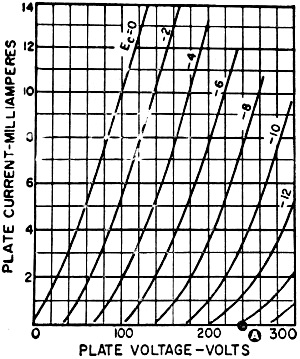 "Can you write a simple equation to express
what I just described, Larry?"
"Can you write a simple equation to express
what I just described, Larry?"  Larry spoke half to himself and half to Ken.
"If the plate voltage is 240 volts and the load resistor is 22,000 ohms, I want
to find out what current would have to flow through 22,000 ohms to give an IR drop
equal to 240 volts." He took the pencil, wrote out the Ohm's law equation for this
situation, and used some simple algebra.
Larry spoke half to himself and half to Ken.
"If the plate voltage is 240 volts and the load resistor is 22,000 ohms, I want
to find out what current would have to flow through 22,000 ohms to give an IR drop
equal to 240 volts." He took the pencil, wrote out the Ohm's law equation for this
situation, and used some simple algebra.  "That's another place where most tube manuals
prove they're worth the money." Ken replied. He flipped through the little book
to the section labeled "Resistance-Coupled Amplifiers" and showed it to Larry. "This
section lists all the amplifier tubes and gives you the dope on typical plate voltage
supplies and plate resistances to use."
"That's another place where most tube manuals
prove they're worth the money." Ken replied. He flipped through the little book
to the section labeled "Resistance-Coupled Amplifiers" and showed it to Larry. "This
section lists all the amplifier tubes and gives you the dope on typical plate voltage
supplies and plate resistances to use." 
|
||||||||||||||||||||||||||||||||||||


