|
|||||||||||||
 |
|||||||||||||
Mechanical Meter Movements
|
|||||||||||||
Mechanical meter movements have been around since the late 1800s. In 1882 Jacques-Arsène d'Arsonval and Marcel Deprez developed a meter movement with a stationary permanent magnet and a moving coil of wire which survives today as the dominant form. Lord Kelvin's (aka William Thompson) galvanometer preceded d'Arsonval's by a decade or so, but it relied on the Earth's magnetic field and needed to be properly oriented to work. d'Arsonval's movement incorporated a permanent magnet instead to improve sensitivity and convenience. I'm not sure d'Arsonval gets sole billing on the name - why not the Deprez movement? This article in Popular Electronics magazine from 1960 is as relevant today as it was more than half a century ago. Meters By Ken Gilmore
This most basic of all test instruments has actually not undergone a single change in fundamental theory or design since 1888. It was in that year - almost 20 years before the invention of the triode vacuum tube - that Edward Weston developed the device we now know as the Weston movement. The Weston Movement Figure 1(A) shows a single coil of wire suspended between the north and south poles of a magnet. Figure 1(B) is a cross section of this setup; the arrows indicate the direction of the magnetic lines of force. When current begins to flow in the wire, a magnetic field forms around it as shown by the small circles. This field opposes the field of the permanent magnet so that the coil is forced to rotate as shown. Since the force generated by one turn is very weak, many turns are used in practical meters.
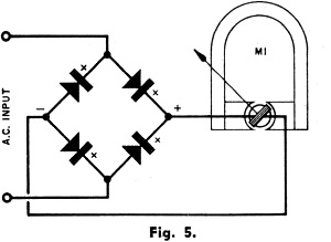
Mechanical meter movements Figure 2 shows such a coil with a needle attached to it; the needle moves along a calibrated scale as the coil rotates. The distance the needle moves is proportional to the amount of current flowing. In other words, if 0.5 ma. generates a magnetic field powerful enough to deflect the needle to half scale, then 1 ma. will cause full-scale deflection. Figure 3 shows the actual construction of a Weston movement - the moving coil (A), a magnet and core (B), and the complete movement (C). Only one aspect of the Weston movement has changed with succeeding years. (See Fig. 4). Development of better magnetic steels has allowed designers to make a more compact instrument by putting the magnet inside the moving coil; the iron shell around the coil completes the magnetic path.Bear in mind that the Weston movement is a d.c. instrument. If a.c. is applied, the needle will try to follow each reversal of the current. But since it cannot move fast enough, it remains in one place and vibrates. But the Weston movement can measure a.c. currents with the addition of a simple rectifier. Figure 5 shows the basic full-wave circuit commonly used. This ability of a Weston movement to respond to either a.c. or d.c. current - with the proper circuitry - makes possible one of the most useful test instruments in electronics: the multimeter. (See Fig. 6.) By adding a handful of resistors, rectifiers, and switches to the meter movement, we come up with a versatile instrument that can measure not only a.c. and d.c. current, but also voltage and resistance. Measuring Current
Mechanical meter movement diagram.
Mechanical meter movement magnet. Let's suppose we have a meter with a basic 1-ma. movement. This means that if 1 ma. of current flows through the coil, the needle will be deflected to its full-scale reading. But say we want to measure a current of 2 ma. We can do it by using a "shunt." To our British friends, this word means a railroad siding. In electronics, it also means a siding, but one for electrons rather than trains. In Fig. 7, the resistance of shunt RS1 is equal to the resistance of the meter (Rm). Thus, half the current (Im) will flow through the meter, the other half (Is) through the shunt, and the full-scale deflection of the needle represents 2 ma. Shunts are easily calculated if we know the meter's internal resistance (Rm). In this case, let's say Rm = 100 ohms. Thus, RS1 in the example given would also be 100 ohms. If the shunt were 50 ohms (RS2), twice as much current would flow through the shunt as through the meter. The meter would conduct only one-third the total current, and its full scale deflection would represent 3 ma. If the shunt were approximately 11 ohms (RS3), nine times as much current would flow through the shunt as through the meter, or, conversely, one tenth the total would flow through the meter, and the full-scale sensitivity would be 10 ma. Modern multimeters have a number of different shunts which can be switched into the circuit to give different current ranges. One typical meter on the market, for example, has scales of 1.5 ma., 15 ma., 150 ma., 500 ma., and 15 amperes. Incidentally, the shunting circuits work the same way in both a.c. and d.c. circuits; the only difference is that a rectifier must be in the circuit for the meter to read a.c. Measuring Voltage
Mechanical meter movement coil.
Mechanical meter movement diode bridge for AC input.
Typical multimeter with mechanical movement.
Mechanical meter movement range selection schematic.
Schematic for meter movement.
Measuring external resistance.
Printed circuit meter movement.
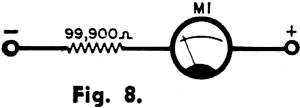
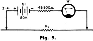
Meter movement product applications. So far, we have considered only current measurements. But a meter can be connected to measure voltage as well. Let's take that same basic 1-ma., 100-ohm meter movement again and make a voltmeter out of it. By using Ohm's law, we can find the voltage which must be applied across the meter terminals to make a 1-ma. flow: E = IR; E = .001 x 100; E = .1 volt. If more than .1 volt appears across the terminals, more than 1 ma. will flow through the meter and damage or destroy it. But suppose we want to measure 100 volts. Again, we apply Ohm's law to find out what resistance the meter would need for only 1 ma. to flow if 100 volts were applied: R = E/I; R = 100/.001; R = 100,000 ohms. Since the basic movement is only 100 ohms, we simply add the 99,900 ohms to make up the total of 100,000 in series with the movement as shown in Fig. 8. With various resistances switched into the circuit, one meter can measure a wide range of voltages. One typical commercial meter, for example, has ranges of 1.5 volts, 5 volts, 150 volts, 500 volts, 1500 volts, and 5000 volts. Again, both a.c. and d.c. voltage ranges can be measured by switching in the rectifier for alternating current. Measuring Resistance A basic meter movement can even be made to measure resistance, but this requires an additional circuit component - a battery. Let's take our 1-ma., 100-ohm meter movement and connect a 50-volt battery in series with one of the leads, as shown in Fig. 9. Again, Ohm's law comes into the picture. We know we have 50 volts in the circuit, and the meter movement must not conduct more than 1 ma., so we can calculate the minimum resistance that must be included in the circuit to limit the current to a 1-ma. value: R=E/I; R=50/.001; R=50,000 ohms. Since the meter already has an internal resistance of 100 ohms, we need add only the other 49,900 in series (R1). Now if we short the two test leads together, 1 ma. of current will flow and the meter will read full scale. Any additional resistance introduced into the circuit will cause the meter to read somewhere between full scale and zero. A relatively low resistance (Rx) between the test leads, for example, would perhaps make the meter read nine-tenths full scale; a larger resistance would make it read half scale; with an infinite resistance, no current at all would flow. Thus, we see that zero ohms appears on the right end of the scale, or opposite from the zero of the volt and ampere scales. Because of the inherent characteristics of the ohmmeter, the needle becomes more and more inaccurate as it approaches the left side of the scale. Therefore, technicians usually try to take resistance readings as near the center of the scale as possible, to obtain the most accurate readings. They do this by switching to various ranges, which, in turn, means switching batteries of different voltages into the circuit. In practice, also, a small variable resistor is usually included in the ohmmeter circuit to compensate for variations in battery strength. The knob controlling this resistor is usually labeled "Ohms Adjust" on the front panel of the multimeter. Other Uses The basic Weston movement can be incorporated into still other kinds of circuits containing vacuum tubes. These instruments have certain advantages over the conventional multimeter just described, and are particularly useful for some types of work. (See Test Instruments: The Vacuum-Tube Voltmeter; April, May, July, 1959, P.E.) Except for certain kinds of vacuum-tube voltmeters, all multimeters have one great shortcoming: they can measure a.c. voltages at relatively low frequencies only - up to about 20,000 cps. But radio and television stations and other branches of communications must measure r.f. voltages and currents up to hundreds of megacycles. This is done with the help of the thermoelement - two tiny chunks of metal, frequently constantan and platinum, clamped together. When the metals are heated, they generate a small voltage across the junction between them. Thus, a circuit can be designed so that r.f. voltage flowing through a separate conductor will heat the junction, which then generates a voltage proportional to the amount of heating. This current is measured by a Weston movement, calibrated in terms of r.f. current. Designers, using the Weston movement as the basic indicator, have come up with an astonishing bag of tricks over the years. With the addition of a light-sensitive selenium disc, for example, as shown in Fig. 10, the device becomes a commercial photographic exposure meter - the brighter the light on the disc, the more current generated. A small generator, on the other hand, transforms the meter into a tachometer for measuring rpm. In another application, two meters in one case can be connected to the electronic receivers in an aircraft instrument landing system and arranged so that they show the pilot whether he is on or off course (Fig. 11). Such meter applications are virtually endless. New Developments. Although the basic Weston movement has not changed in principle or basic design for 72 years, there are many striking new developments in meters. One of the newest is a printed-circuit meter recently introduced by the Parker Instrument Division of Interlab, Inc. As shown Fig. 12 the meter's coil is printed on a thin disc and mounted parallel to a ring magnet. When current flows through the printed-circuit coil, a magnetic field is created which reacts with the field of the magnet, and makes the disc rotate. A soft iron shell (not shown) encloses the magnet and disc, furnishing a return path for the magnetic lines of force. The entire printed-circuit meter is only 1/2-inch thick. And since it weighs only a fraction as much as conventional meters of similar sensitivity and range, it will undoubtedly find widespread use where size and weight are important - in airborne equipment, for example. Another important advantage of the new movement is its ability to handle overloads that would instantly burn out the relatively delicate Weston movement. The manufacturer claims that an overload of 1000 to 5000% will not damage these movements. Another relatively new development is the meter which triggers a relay. Here, the indicating needle is fitted with a contact. A matching contact is fastened to an arm which is adjustable from the front panel. When the current in the circuit under measurement causes the needle to deflect to where the adjustable arm has been pre-set, the two contacts come together and set off a sensitive relay which can then be used to control some other circuit. By far the most sensitive relays available, these instruments can be made to operate on as little as one or two microamperes. Units of this type, by the way, can be used in any kind of control circuit- battery charging, tube overload protection, etc. - anywhere fast, accurate control is needed. But developments such as these only scratch the surface. As the science of electronics advances into new realms, scientists and engineers are constantly finding new ways to make the basic meter - oldest of all electronic test instruments - more and more useful.
Posted January 5, 2023 |
|||||||||||||
 |
|||||||||||||
|
|||||||||||||


|
||||||||||||||||||||||||||||||||||||


