|
|||||||||||||
 |
|||||||||||||
The Possible Impractical Impossible Circuit
|
|||||||||||||
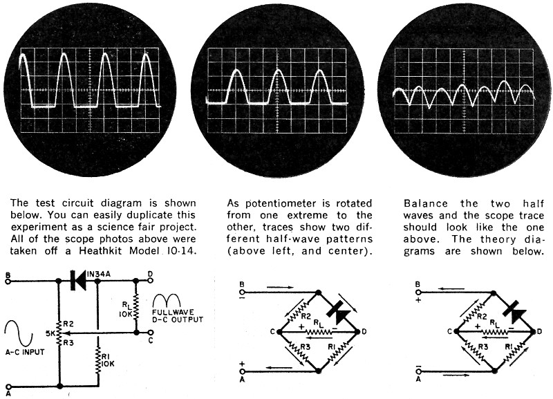
Can a single diode be used to constitute a full-wave rectifier circuit? The short answer is yes, it can, as is demonstrated by an actual circuit built by Messrs. Duffy and Olesky. The real question is can a single-diode full-wave rectifier be used in a practical circuit? Under certain controlled instances it can as long as component values and tolerances for both the power supply and the load can be controlled acceptably. High impedance, ultra low current circuits in today's marketplace are more likely to be able to support the single-diode rectifier, but then so many products are composed of a single integrated circuit that can easily include an internal two- or four-diode full-wave bridge that such a money- and space-saving scheme is not necessary. Still, it is an interesting theoretical study. The Possible Impractical Impossible CircuitWould You Believe a Single-Diode Full-Wave Rectifier? By Tom Duffy and Jerry Olesky A one-diode full-wave rectifier? Impossible! Everyone knows you need at least two diodes for full-wave rectification. Or, should we say, everyone assumes that you need two diodes. You can demonstrate one-diode full-wave rectification with the circuit shown below, left. The frequency of the input is relatively unimportant. Connect an oscilloscope across output terminals D and C and you should get one of the three waveforms shown, depending upon the position of the potentiometer arm. With the potentiometer arm at the top, the waveform should be like the one at the extreme left. Rotating the arm to the other extreme should produce a waveform like the one in the middle photo. If you carefully balance the two waveforms (via the potentiometer), the output should become a typical full-wave rectification pattern (right). The two theory schematics (center and right) show what's happening. When terminal B is negative with respect to A, the current flow is indicated by the arrows. Note that current goes through the rectifier and through the load resistor. When the polarity of the input is reversed, current flow through the rectifier is blocked, but a new path is formed through resistor R1 and current continues to flow through the load. Thus, no matter what the sine-wave excursions are, the direction of flow through the load resistor is the same - hence, you have full-wave rectification. Why isn't this circuit used in practical everyday equipment? Well, in a conventional full-wave rectifier the efficiency can go up to 90%, but in this one-diode arrangement the efficiency is only about 25%. Also, all of the resistors are in series with the load and any voltage drop across them will subtract from the output.
(left) The test circuit diagram is shown below. You can easily duplicate this experiment as a science fair project. All of the scope photos above were taken off a Heathkit Model 10-14. (middle) As potentiometer is rotated from one extreme to the other, traces show two different half-wave patterns (above left, and center). (right) Balance the two half waves and the scope trace should look like the one above. The theory diagrams are shown below. |
|||||||||||||
 |
|||||||||||||
|
|||||||||||||


|
||||||||||||||||||||||||||||||||||||


