|
|||||||||||||
 |
|||||||||||||
Telemetering - Vital Link to the Stars
|
|||||||||||||
Telemetering - the remote sensing and reporting of system parameters via radio link - was just coming of age in the late 1950s when this article appeared in Popular Electronics magazine. It was the age of space payload rocket development (as opposed to artillery and fireworks rockets), high speed jet airliners, and the Pioneer 1 space probe. There was a great need to collect data during the developmental and operational engineering project stages in order to ascertain causes for failures when they occurred and to know what went right when success triumphed. A pinnacle of the newborn telemetering era was Pioneer 1, which carried an image scanning infrared television system to study the Moon's surface to a resolution of 0.5 degrees, an ionization chamber to measure radiation in space, a diaphragm/microphone assembly to detect micrometeorites, a spin-coil magnetometer to measure magnetic fields to 5 microgauss, and temperature-variable resistors to record the spacecraft's internal conditions*. Unfortunately, the launching rocket experienced a malfunction that buggered the flight trajectory, but the craft still managed to return some useful data. In that instance engineers benefitted from both success and failure telemetering. Telemetering - Vital Link to the Stars 
Of little importance until recently, telemetering is now one of the latest-growing fields in electronics. By Earl Stowell A 100-ton 85·foot missile fights its way up into the sky, arches proudly out over the ocean, falters, veers wildly, becomes a surging spectacle of flame, then plunges into the ocean. After the scientists recover from their disappointment, how can they find out what caused the failure? The answer is telemetering - the process of taking measurements at one place and simultaneously sending them to another place for interpretation or "read-out."Telemetering should not be confused with remote control. When you set the temperature control of a modern stove, you are using a type of remote control to regulate the oven temperature. But if the stove has a signal lamp that goes on when the correct temperature is reached, this is a form of telemetering - because information (the temperature) is measured at one place and is then sent to another for "read-out." Sending Back the News
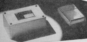
Telemetering components are always compactly packaged. Above is a transistorized subcarrier oscillator made by United Electrodynamics.
A Parsons crystal-controlled two-watt FM transmitter.
A telemetering r.f. amplifier. This Rheem unit covers 215 to 245 mc.
Ground installation is last link in telemetering chain. High-gain antennas, such as the 60' "dish" above by Radiation, Inc., feed signals into elaborate electronic "brains."
First two racks of Parsons ground system contain tape recording equipment; in the third rack are receivers and test equipment; the next two hold bandpass filters and discriminators; racks 7 and 8 are demodulators and patch-panel racks; the next-to-last one contains oscilloscope and associated equipment; rack at far right holds five strip recorders. Only in recent years has there been a need for telemetering. In the early days of flying, for example, when planes were much simpler than they are now, a test pilot would take a new plane up for its initial run and would then report back to the designers what changes should be made. But nowadays things happen so fast on test flights that it's impossible for the pilot to notice everything that's going on. And today's aircraft are so expensive and complex that if an accident occurs, a method of determining the reason for the accident is essential. Telemetering provides the means for solving these very real and important problems. Weather-study instruments developed in the Thirties provided a clue for the design of telemetering equipment. A German scientist devised a simple but effective system for determining atmospheric conditions at various altitudes. He attached a battery-powered radio transmitter to a balloon and then hooked up some sensing elements to it that delivered varying voltages in proportion to altitude, temperature, and humidity. As the balloon floated through the sky, a three-point rotating switch connected each of the instruments in turn to the transmitter. Even today, this simple technique forms the basis of many telemetering systems. Instrumentation Telemetering systems seem complicated, but their complexity comes from the amount of detail involved, rather than from their inherent circuit complications. The first links in a telemetering chain are the measuring instruments, which are designed to produce output voltages in ratio to their readings. For instance, to measure temperature between 0° and 100°, a measuring instrument with an output range from 0 to 5 volts would deliver no output at 0° and 5 volts at 100°. A temperature of 50° would result in an output of 2.5 volts. It is more common, however, to use a measuring instrument that puts out ±2.5 volts, with zero representing half-scale; hence, -2.5 volts would indicate a temperature of 0° and +2.5 volts would mean 100°. These voltage variations from the measuring instruments must be coded before they are fed into a transmitter. For example, information can be indicated by varying the duration of the pulse; this method is called PDM (Pulse Duration Modulation). Or the amplitude of the pulse might be varied (PAM, or Pulse Amplitude Modulation). Another method is PCM (Pulse Code Modulation) or its close relative PPM (Pulse Position Modulation) in which the position of two short pulses with relation to each other is the code. For extreme accuracies, a digital system is used. In this system, each measurement is changed to a binary number which may then be handled with high accuracy - up to 0.01% if required - and the output can be fed directly into a digital computer. Final Link At the ground station, specially designed antennas pick up the r.f. signals which are demodulated, sorted out, and turned into understandable form. In some cases, the signals are decoded as fast as they are received; this is called "real-time" telemetering. Most of the information is recorded by tape recorders for later study. Some advanced telemetering systems feed selected information directly into computers for immediate processing, as mentioned above, making it possible to notify a pilot of danger developing before he is aware of its presence. Because telemetering installations are usually tailored to a particular job, there are as many telemetering systems as there are engineers with imaginations. But if you know the general principles involved, you will be able to understand any telemetering system with a little study. Problem and Solution Let's take a typical telemetering problem and then follow through on its solution. Assume that we want to send up a missile for testing. Since it's doubtful that the missile will return to the ground in one piece, we must get the information we need while the missile is in flight. Suppose we want to know its angle of flight, speed, yaw and pitch rates, the level of gamma rays encountered by the missile, and various other measurable data. Now, how do we get this information? We start by building a battery-powered FM transmitter into the missile. Then, if we have many measurements to send back to the ground, we can use a combination of two frequency-saving methods of feeding the transmitter. First, we use subcarrier oscillators to create multiplex subchannels. Some systems use up to 18 subchannels - all of which can be handled by the same transmitter. For instance, if the first subcarrier oscillator (SCO 1) has a center frequency of 400 cps, a ±2.5-volt input signal from the sensing element will cause SCO 1 to vary from 370 to 430 cps. Accordingly, SCO 18 has a center frequency of 70 kc., and its output frequency will vary from 64.75 to 75.25 mc. The outputs from the SCO's all modulate the FM transmitter simultaneously and the receiver on the ground sorts out and decodes the different SCO frequencies. Secondly, one or more SCO's can perform multiple service by means of a simple mechanical" system. A rotating switch with multiple contacts can be wired up to connect several sensing elements to a single SCO one at a time. As a small external motor rotates the switch, each sensing element is sampled in order. See block diagram on page 43.
Block diagram of typical telemetering system. Subcarrier oscillators all modulate transmitter simultaneously. SCO 4 does multiple duty by sampling four different measurements in order when commutator turns.
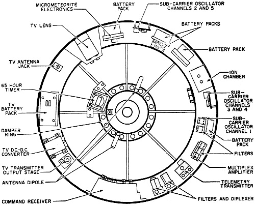
Cross section of telemetering pay load carried by the "Pioneer I." Although short-lived, the "Pioneer I" provided a great deal of data. In the event that the missile should be recovered intact, it's a wise precaution to include a small tape recorder in the airborne system. Should the transmitter go off the air for any reason, the recorded tape would be vitally important. Expensive but Economical Although telemetering systems are fairly expensive, in our rocket projects they more than pay their way. Telemetering makes each test flight - no matter how apparently disastrous - at least partially successful. Design weaknesses can be analyzed long after the flight is over, and troubles can be ironed out before another test is attempted. In industry, too, telemetering pulls its own weight. Recently, a major airframe company spent two million dollars for telemetering equipment to be used in testing jet transport planes. The saving in test time will easily pay for the system. Telemetering offers a rapidly growing field to those who like something new and exciting. To the rest of us, it promises safer flying and information which will speed our conquest of outer space.
Posted January 25, 2023 |
|||||||||||||
 |
|||||||||||||
|
|||||||||||||


|
||||||||||||||||||||||||||||||||||||


