|
|||||||||||||
 |
|||||||||||||
Understanding Ungrounded Oscilloscope Measurements
|
|||||||||||||
Those of us who have been making measurements on electrical and electronics equipment for a long time are well aware of the need to be certain that the ground (common) lead of a piece of test equipment - oscilloscope, multimeter, or other instrument - is never connected to a point in the circuit that is above ground potential. Doing so can be dangerous and/or destructive. If the test point is above ground potential, connecting the ground lead to it creates a direct short to ground, which can destroy the device under test (DUT) or at least cause the measured signal to be altered. In the case where the DUT has no ground reference of its own via a safety ground connection, connecting the ground lead to a point not electrically common to the chassis (or enclosure) will cause the chassis to assume a potential other than ground. Many technicians received shocks (sometimes fatal) while servicing old ungrounded (2-prong power cord) TVs that did not have isolation transformers at the input. Connecting a meter between a set of transformer secondary windings where neither had a direct connection to the chassis would cause the chassis to "float" to a potential above or below ground (depend on polarity), sometimes to lethal levels. Understanding Ungrounded Oscilloscope Measurements
Fig. 1 - In transformerless circuit, ground return on point V can a short across Y-Z element. By Virgil A. Thomason Making scope measurements across ungrounded components can present some problems. Here are the reasons - and some answers. When we measure a voltage in a circuit, we don't always take into account what we are actually measuring. For instance, we might say that a power supply's output is 50 V dc with 0.75 V ac ripple; or the output signal at a transistor amplifier's collector is 5 V ac. In these, and just about all voltage measurements, what we really mean is that the power supply's output is 50 V dc with respect to ground (or chassis common); the ripple is 0.75 V ac with respect to ground; and the amplifier output is 5 V ac with respect to ground. Thus, what we are really measuring is the voltage at a given point - with respect to a common point. Since a voltage is the potential difference between two points, the two points have to be identified. For convenience, we generally use chassis ground as the second point. But what if we want to measure the voltage across a component both sides of which are above ground? This presents a problem - many problems, in fact. Obviously, one difficulty is the lack of a convenient, easy-to-get-at chassis for a connecting point. More important, however, are the possible bad effects of connecting both leads of a test instrument to ungrounded points. Of course, occasions such as this do not occur often; but when they do, knowing the proper procedure can make the job easier and prevent undesirable effects such as overloaded circuits and noise pickup. Not a Simple Test. Measuring a voltage between two ungrounded points is not always a simple matter. Assuming that an oscilloscope is being used, one does not merely connect the test probe and ground lead at opposite ends of the ungrounded component - certain precautions must be observed. Consider the following examples. Assume that we have a conventional scope which has a three-wire power cord. For safety, the scope chassis is tied to the third wire and ground. Because the signal input "ground" terminal is also common with the chassis ground, it too is tied to the third wire in the power cord. Now, let's say we're testing an ac/dc radio or a transformerless TV receiver; the chassis being tested is tied to the low side (ground) of the power cord. So we have the situation shown in Fig. 1. The chassis are tied together through the power line system.
Fig. 2 - With power transformer in circuit, connecting scope ground return to point V can put an ac shunt across V-Z. As long as the scope's ground test lead is connected to the tested chassis (point Z in Fig. 1), the chassis are tied together, the grounds are tied, and we have a good, safe test setup. Notice, however, what happens when the scope's ground test lead is connected to a point above ground potential (point Y in Fig. 1). The portion of the circuit between Y and Z is effectively shorted out by the ground circuit through the two chassis and the power line ground. This, of course, could severely disturb the circuit operation and possibly damage the components in the network. The same ground problem could also occur with a scope that has a 2-wire power cord if the low side is tied to chassis ground. Now, assume that we have a scope with a three-wire power cord and we're testing a TV receiver with a power transformer and a conventional 2-wire ac connection. As shown in Fig. 2, the low side of the ac line is connected to the chassis through a large resistance (commonly 2.2 megohms). Of course, not all equipment have this resistance - some are entirely isolated - but it is important to know whether it is there or not. With the circuit shown in Fig. 2, there is an ac shunt effectively placed across part of the circuit under test. The ac path inside the receiver is from point Z to the chassis, to the transformer secondary, through stray primary-to-secondary capacitance, to the transformer primary, to the ac line. This ac shunt can cause problems, especially with high frequency measurements. (For all of the above situations, tying the ac line to an ungrounded point can introduce noise into the circuit.)
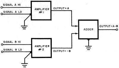
Fig. 3 - Simple differential amplifier has inputs A and B and output A-B. Still another problem is encountered if the scope does not have its chassis tied to the power line ground. In this case, connecting the scope ground lead to a point above ground could make the chassis "hot." So there are several undesirable effects that we want to avoid - dc shunt, ac shunt, noise pickup, hot scope, etc. Let's examine ways to make ungrounded measurements. Conventional Scopes. The only way to get ideal ungrounded measurements is with a special scope with a differential amplifier input. Next best is to use a scope with a dual-trace amplifier input and an "A-B" mode. But even with a conventional scope, there are ways to reduce some of the undesirable effects - if not completely eliminate them. First, we must know our scope. Is the chassis grounded to the ac line? Also, note the grounding on the device under test. If it has been determined that the scope will not cause a dc shunt, we must realize that the circuit being tested can still be disturbed by the scope's ac loading. Noise and hum pickup should be taken into account. Even if the scope chassis is not directly tied to the line ground, it can put noise into the tested circuit; the scope's large metal cabinet acts as an antenna and picks up noise. We can use an isolation transformer with the scope to prevent dc shunts. This also reduces the ac shunt; but because of the transformer's primary-to-secondary capacitance, ac loading and noise will still occur. However the capacitive reactance does reduce loading and noise - as compared to a direct line without a transformer. In using an isolation transformer, remember that the scope chassis can be hot when the signal ground lead is connected to an ungrounded point.
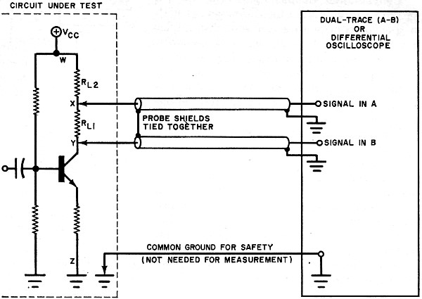
Fig. 4 - Using a differential scope to make a measurement across an ungrounded component. Oscilloscope Differential Amplifier. Because the output of a differential amplifier is the difference of its inputs, we can use it to measure the voltage across a component-which is a potential difference. The significance of a differential voltage measurement is that it can be used for an ungrounded component without encountering the bad effects noted above. Figure 3 shows a simplified block diagram of a differential amplifier. It consists of two identical amplifiers. They have the same gain, but one inverts its input. The outputs are then combined by algebraic addition; and since one output is inverted, the total is A - B. Differential measurements are less common than conventional single-input measurements so scopes with differential amplifier inputs are few. Many scopes of the plug-in type have differential amplifier inputs. The electronics enthusiast, experimenter, or service technician could build a differential amplifier to feed a conventional single-input scope. In practice, the signal high leads are connected to the two points to be measured. No common ground connection is required so the two low leads are not used. Usually, they are shields on the test probes. For safety reasons, however, the scope and device under test may be connected with a grounding wire. However, this connection must not be the signal low leads or the shields, to avoid ground loops. It should be pointed out that the differential amplifier scope is not the same as a dual-trace scope. The latter has two amplifiers, each with its own input. Electronic switching alternately feeds the output of each amplifier to the scope's vertical deflection section. The result is a simultaneous display of the two inputs.
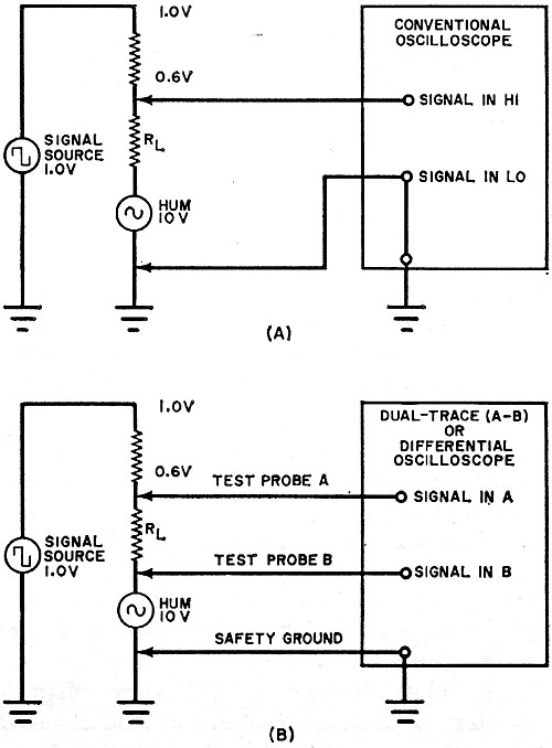
Fig. 5 - Conventional scope (A) displays both signal and hum, while a differential scope (B) displays only signal across the load resistor. Under certain conditions, a dual-trace scope can provide some of the benefits of a differential amplifier scope. For instance, if there is an A - B mode and the amplifiers are well matched, the difference of the two inputs is displayed. The scope manufacturer's operation manual will explain this function where applicable. Making Differential Measurements. Let's see how differential scope measurements are made for ungrounded tests. In the circuit shown in Fig. 4, we want to measure the signal across load resistor RL1. Only the high signal leads are connected to the circuit under test (at points X and Y). The shields are connected together and grounded; but they are not grounded at the tips. This connection reduces the impedance of the loop formed by the shields and equalizes the currents through the loop, thereby allowing the differential amplifiers to nullify loop current effects by common mode rejection. It is not correct to tie both shields together at the probe end and also connect them to the chassis. This makes a circuit for ground currents through the shield and can create measurement errors because of voltage difference at the scope. It would also be wrong to leave both shields unconnected at the probe ends. This would permit the shields to act like antennas to pick up noise. The probe tips represent a high impedance to the circuit being tested and do not introduce excessive loading as did the conventional test circuits shown in Figs. 1 and 2. Since the scope chassis is not tied to a signal high point, there is no ac line noise introduced. Reject Common Mode Signals. One of the more important uses of a differential measurement is to reduce the effects of a common mode signal such as hum. Common mode signals are identical with respect to amplitude and time. Since the output of a differential amplifier is the difference between its two inputs, a common (identical) signal on each input will be reduced (but not eliminated) in the output. There is a limit as to just how effective a differential amplifier can be. Its ability to reject common mode signals is known as common mode rejection. The ratio of the common mode input signal amplitude to the amplitude of the difference signal displayed on the scope is known as the common mode rejection ratio. The higher the ratio, the better the differential amplifier.
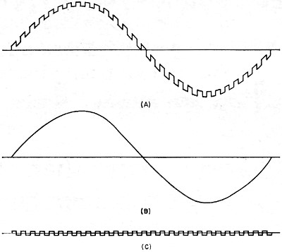
Fig. 6 - (A) Signal with hum; (B) hum alone; (C) signal with hum rejected. For example, if the common mode signal on both inputs is 10 volts and the signal produces a scope display of only 0.01 volt, the common mode rejection ratio is 10/0.01 or 1000. Note what happens with a conventional scope measurement as shown in Fig. 5A. There is an unwanted 60-Hz hum signal in the circuit along with the desired signal. Assume the hum is 10 volts and the square wave source is 1 volt, of which, 0.6 volt appears across the component being tested. With the conventional scope setup, both the 0.6-volt signal and the 10-volt hum would be displayed, as in Fig. 6A. The desired signal rides on the bothersome hum, making the measurement difficult. But notice what occurs when a differential scope is used as in Fig. 5B. In test probe A, is the combined signal and hum; while the hum alone is in probe B. The scope displays A minus B or only the desired signal across the resistor as shown in Fig. 6C. The amount of hum that is rejected depends on the scope's common mode rejection ratio; and if the latter is good, the resultant signal would have negligible hum. As we have pointed out, the A - B mode of a dual-trace scope can be used for differential measurements. The common mode rejection of such a scope, however, is less than that for a differential amplifier scope. Nevertheless, the ability to reduce common mode signals to even a small degree would be all that is needed for making a good measurement. Posted February 7, 2018 |
|||||||||||||
 |
|||||||||||||
|
|||||||||||||


|
||||||||||||||||||||||||||||||||||||


