|
September 1970 Popular Electronics
 Table of Contents Table of Contents
Wax nostalgic about and learn from the history of early electronics. See articles
from
Popular Electronics,
published October 1954 - April 1985. All copyrights are hereby acknowledged.
|
Even if you no
longer - or never did - have the need to wind your own audio frequency output
impedance matching transformers, this article from a 1970 issue of Popular
Electronics magazine provides good insight into the factors necessary for
consideration when doing so. One particularly nice feature here is that power
handling is taken into account, including wire size to use for the primary and
secondary (or multiple outputs). At audio frequencies, where the
transformer is driving speakers with typical impedances of 4, 8, or 16 ohms, you
do not need to worry too much about parasitic capacitance and inductance. The
basic equations do a pretty good job of predicting performance. Author Ed
Francis explains how to modify a junk-box laminated core transformer to work, as
well as providing a table of enameled wire size ampacities and turns per linear
inch. An example of how to perform all the steps is given.
For Improved Matching and Power Handling
 By Ed Francis By Ed Francis
Circuits involving solid-state components frequently
require "non-standard" audio output transformers. This article describes simplified
methods of calculating the primary/secondary ratios, wire sizes, and numbers of
turns for low-impedance matching transformers wound on "salvaged" cores.
Project Builders and experimenters occasionally need a small impedance matching
audio transformer with an uncommon impedance ratio. When such a transformer is specially
wound, its cost is usually prohibitively high compared to the total cost of the
project in which it is to be used. However, with a few calculations and a little
work on your part, you can duplicate many unusual transformers or and special audio
coupling or matching transformer to suit your needs. The techniques prescribed in
this article are limited to transformers of average size and low-to-medium impedance.
It is impractical to duplicate subminiature transformers that normally cost only
$1 or less and high-impedance transformers that require many turns of very fine
wire.
Throughout tins article, you will find the term "volt amperes" (VA) used in the
same manner that "watts" is used for power. This usage involves an assumption which
is not quite true. However, for this type of work, if you accept the assumption
that the two are equal, the results will be acceptable.
Calculations involved in designing an audio transformer are covered by the nine
steps outlined in the box on page 81. To see how these steps work, let's design
a typical transformer. Assume that a transistor output transformer with a 130-ohm
primary and a 4/8/16-ohm secondary is needed to match the output of an RCA CA3020
IC to a loudspeaker. By referring to the mail-order catalogs, we find that the full
output of the IC is 0.5 watt. The nearest thing you can find in the catalog is a
125-ohm center-tapped transformer rated at 300mW. This transformer could be used,
but, you can make one that will be. just as good and design it for a full watt if
space and weight requirements permit.
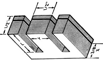
Fig. 1 - Calculate X dimension needed to provide core area when
multiplied with Y dimension; then, as indicated by heavy lines, remove required
number of metal laminations.
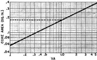
Fig. 2 - Lengthy mathematical computations for determining the
transformer core area can be avoided with the aid of the graph shown here.
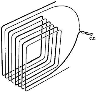
Fig. 3 - Bifilar winding technique precisely locates center-tap.
Center-tap is derived by twisting together opposite ends of winding.

Wire Table
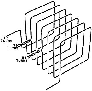
Fig. 4 - Individual taps are obtained by twisting short pigtails
from continuous length of wire. Attach stranded wire leads to pigtails.

Fig. 5 - Although not really necessary if you followed all steps
carefully, the finished transformer can be tested as shown in drawing.
First calculate the core area required. Note, however, that tile core area applies
only to the cross-sectional area of the core's center leg as shown in Fig. 1. Referring
to Fig. 2, we find that the graph shows an approximate core area of 0.18 sq. in.
will snit our requirements. (We can use an approximation since the actual core area
is not too critical.)
Determine the turns ratio from the impedance ratio. Since we know the primary
and lowest secondary impedances to be used, plug 130 and 4 into the equation: Ratio
= the square root of (130/4):1 = 5.7:1. Hence, the actual turns ratio required shows
5.7 turns in the primary winding for every turn in the secondary winding.
Next, determine the d.c. voltage to be applied to the transformer's primary.
In this ease, we desire 9-volt operation. The CA3020 employs a push-pull. output.
So, bear in mind that an 18-volt figure must be used in all primary calculations.
Calculate the wire size needed for the primary winding. Since we have decided
to design the transformer to handle 1 watt of power, let us first determine how
much current will be handled by the primary: I = (VA/Vcc) = 1/9 = 0.111 A.
Now, because of the push-pull division of the current, we divide the primary current
by two for determining the wire size; this gives us 55 mA in each half of the
primary winding. If 700 circular mils/ampere is desired, refer to the Wire Table
(column four) on page 80, and locate the current at or greater than 55 mA.
Column one shows that #34 wire will safely handle 57 mA, the nearest figure
to 55 mA. This size is quite small and difficult to work with, so choose #28
wire for ease of winding.
We will have to make some assumptions now in determining the number of primary
turns to be used. For this calculation, we will use 2Vcc, or 18 volts, and an area
of 0.18 sq. in. for our 1-watt transformer. The frequency we will arbitrarily settle
on as being 100 Hz. For flux density BM in gauss/sq. in., any figure between
40,000 and 90,000 can be used; we'll settle on 70,000 to be conservative:
Primary Turns = 2Vcc x 108 / (4.44 x Ax f x BM)
= 18 x 108 / [4.44 x (0.18) x (100) x (70,000)] =
321
so, 320 turns will be close enough.
Having calculated the number of primary turns, we use the turns ratio formula
to calculate the number of secondary turns needed. This is a step-down-type transformer,
so we divide the number of primary turns by t to turns ratio: Secondary Turns =
Primary Turns / Turns Ratio = 320 / 5.7 = 56 turns.
Secondary wire size is determined by the current ratio method. Secondary current
is equal to the primary current multiplied by the turns ratio: 0.111 x 5.7 = 0.64 A.
The secondary wire size is determined by the same method as used for the primary.
At 700 circular arils/ampere, the Wire Table indicates a 577 mA current capacity
for #24 and 728 mA for #23 wire. Since 640 mA is about midway between
the two sizes, we will settle on #23 wire.
Finally, the 8-and 16-ohm taps must be calculated. Again, refer to the turns
ratio formula, and determine the turns ratio for 8 and 16 ohms separately. Then
use these ratios with the primary turns to determine the exact number of turns required
for each impedance: 16-ohm ratio = the square root of (130/16):1 = 2.86:1; 8-ohm
ratio = the square root of (130/8):1 = 4.04:1. Secondary turns = 320/2.86 = 112
turns for the 16-ohm ratio; Secondary turns = 320/4.04 = 79 turns for the 8-ohm
ratio. Hence, the composite secondary will consist of 112 turns of wire with taps
at the 56th and 79th turns.
Now that we have all of the design parameters, we can proceed to assembling our
special-purpose transformer.
Assembling the transformer from the design parameters derived from the above
procedure is easy. We know that the core area must be about 0.18 sq. in. The simplest
and least expensive way of obtaining a suitable core is to salvage an old audio
output transformer. Many such transformers have a core area of 0.25 sq. in. If about
a quarter of the laminations are removed, approximately the correct dimensions will
be obtained (about 0.185 sq. in.).
Disassemble the salvaged transformer, and remove and discard the windings, but
reserve the plastic winding bobbins if it has one. It no bobbin is available, you
can make one from an index card or heavy waxed (butcher's) paper. This bobbin should
easily slide over the core leg and be a little shorter than the center leg of the
laminations.
Slide the bobbin onto a length of wood to serve as a winding handle. Then begin
winding the primary turns onto the bobbin, starting and ending along the 1/2" side
of the bobbin to avoid having the ends exit from the core "windows" when the bobbin
is in place. Ordinary "scatter" winding is acceptable in most cases; but if space
is limited, you might have to close-wind the turns. Our hypothetical transformer
has a further complication: The primary winding is center-tapped. It must be wound
so that both sides of the winding are balanced. To do this we will use the "bifilar"
winding method shown in Fig. 3.
For our 320-turn primary winding, we wind two wires onto the bobbin simultaneously,
side by side, until there are 160 double turns on the bobbin. Then to complete the
bifilar winding, we connect one end of one wire to the opposite end of the other
wire and solder on a 5" length of stranded hookup wire to make the center tap. Two
more stranded wires soldered to the free ends of the primary windings complete the
primary assembly. Color code the wires so that the center tap is easily identifiable.
Make sure that each soldered connection is well insulated from the others; then
wrap a layer or two of plastic tape over the windings.
Now wind the secondary turns onto the bobbin. Count tile turns as you go, and
make a pig-tail tap leads at the 56th and 79th turns for the 4- and 8-ohm taps (see
Fig. 4). Use color coded stranded hookup wires for the winding ends and taps so
that each can be easily identifiable. Again, make s ire that the solder connections
are well insulated from each other, and wrap a layer or two of electrical tape over
the assembly to prevent the windings from unraveling.
Slip the bobbin assembly off the winding handle. Orient the primary leads to
one side and the secondary leads to the other side of the bobbin. Then slip the
bobbin onto the center leg of the transformer core laminations. Assemble the transformer.
Testing the completed transformer is not really necessary if you exercised care
during assembly and followed each step exactly as described. However, if you want
to be on the safe side, von can test the transformer with the aid of an audio signal
generator, two ac VTVM's or FET VOM's, an 8-ohm load resistor, and a 1000-ohm potentiometer
as shown in Fig. 5. Set the generator's amplitude control for an output of several
volts at 1000 Hz. Adjust the potentiometer for mini-mum resistance so that
both meters have an identical reading.
Now, increase the resistance of the potentiometer until meter #2 indicates exactly,
one half its original indication while making sure that meter #1 remains at the
original voltage setting. Since changing the resistance of the potentiometer decreases
the load on the audio generator, meter #1 will indicate an increase in voltage.
Simply reduce the generator's output level to return meter #1 to the original voltage
setting.
After jockeying back and forth between the generator's amplitude control and
the potentiometer a few times, you should be able to arrive at settings where meter
#1 indicates the original voltage and meter #2 indicates exactly half of its original
voltage. When this occurs, remove the potentiometer front the circuit without upsetting
its final setting and measure its resistance. This resistance should be equal (or
as near as possible) lo the transformer's input impedance, or 130 ohms. However,
if the transformer is loaded with an incorrect impedance (say, the 8-ohm load resistor
connected acres the 4-or 16-ohn output leads), it will reflect an incorrect impedance
into the primary. As a matter of tact, if you use a 3.2-ohm speaker on the 4-ohm
transformer output, a primary, impedance somewhat lower than that for which the
transformer was designed will be reflected. But if you plan to rise such a speaker
with the transformer, yon could easily have plugged into the equations the 3.2-ohm
figure for the 4-olun figure.
9-Step Audio Transformer Design Example
In approaching something like the design of your own special-purpose audio matching
or output transformer, you should use a practical, realistic procedure. The nine
steps outlined here are set up so that you will not overlook time and work -saving
steps and will lead you from start to finish without a lot of messy mathematical
calculations.
Step (1). Refer to the catalogs for all available data (such as primary and secondary
impedances and power and voltage ratings) concerning the transformer needed.
Step (2). Determine the transformer core area; from the transformer power rating
(VA), area is equal to the square root of VA divided by 5.58. A quicker method is
to refer to the graph in Fig. 2. Read up from the selected volt-amperes figure to
the diagonal line, project to the left and read the core area in square inches.
Step (3). Calculate the turns ratio. From the impedance ratio, the turns ratio
is equal to the square root of (Z1/Z2), where Z1 is the larger and Z2 the smaller
impedances.
Step (4). Determine the voltage for which the transformer primary is to be used.
For single -ended operation, use supply voltage Vcc; for push-pull operation use
2Vcc.
Step (5). Compute the size of the wire needed for the primary turns. Using the
transformer power rating and the d.c. operating voltage (Vcc), primary current equals
VA/Vcc. For audio service, a minimum of 600 circular mils/ampere is recommended;
winding space permitting, it would be better to figure on using 700-1000 circular
mils/ampere. A center. tapped primary would have only half of the total current
flowing through each half of the winding at any one time, so the metric area can
be reduced by half.
Step (6). Calculate the number of primary turns needed:
Primary Turns = Vcc x 108 / [4.44 x (A) x (f)
x (BM)],
where Vcc is supply voltage; A is core area in square inches; f is the lowest
frequency to be passed without loss; and BM is flux density in gauss/square inch.
Step (7). Determine the number of secondary turns required. If the transformer
is to be an impedance -step up type, multiply the turns ratio by the number of primary
turns calculated; if step-down, divide the primary turns by the turns ratio.
Step (8). Calculate the secondary wire size by the turns ratio method. Current
transfer is inversely proportional to the turns ratio. Hence, if the transformer
is a 10:1 step-down type, the secondary should be capable of handling ten times
as much current as the primary. Once the current capacity is determined, you can
refer to the Wire Table to find the smallest diameter wire that will suit your needs.
It is, however, advisable to use the largest practical size wire to obviate a large
d.c. voltage drop in the windings.
Step (9). If the center tap is required, use the "bifilar" method of winding
(see text). For multi-impedance outputs, recalculate the turns ratios, secondary
currents, etc., for each output impedance.
Posted September 6, 2022
|


