|
|||||||||||||
 |
|||||||||||||
"Printed" Radio Circuits
|
|||||||||||||
Printed circuits were originally printed on onto a substrate material - thus the name "printed." It can be considered an early form of additive manufacturing, similar to printed 3-D objects nowadays. the opposite of additive manufacturing is, of course, subtractive manufacturing. Modern printed circuit boards (PCBs) have metal removed during the etching process, hence, subtractive. When a metal ingot or casting is machined and material is removed, that is subtractive manufacturing. Prior to 3-D printers, had you ever heard of additive manufacturing. Me neither, and for that matter, nobody ever spoke of subtractive manufacturing. But I digress. The early printed circuits like the one featured here in this 1946 issue of Popular Mechanics magazine still used vacuum tubes. In this case the full-size tubes were replaced by peanut tubes, but there were plenty of PCBs that had standard tube sockets mounted to them. Eliminating the time-consuming and error-prone point-to-point wiring in a cramped chassis was worth the extra expense. It paved the way for more extensive use of printed circuits so that the technology was maturing by the time semiconductors came along a decade later. "Printed" Radio Circuits
Assembler solders components on printed circuit board.
Schematic of printed circuit board.
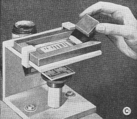
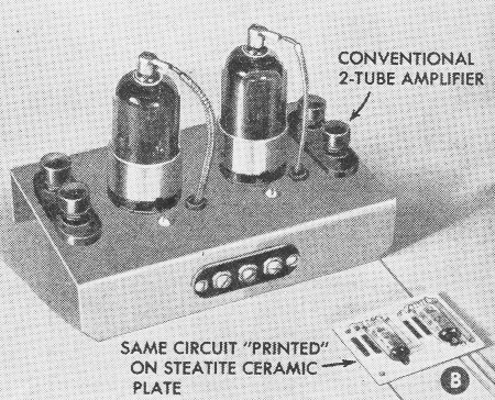
Comparison size chassis wiring versus printed circuit board. Silver lines replace copper wires in the "printed wiring" method for radio circuits that employed tiny tubes used in the proximity fuse, one of the secret war weapons. Developed by the engineers of Globe-Union, Inc., Milwaukee, Wis., this "printed hookup wire" solved a difficult construction problem as it was necessary to design a radio transmitter and receiver small enough to fit on the end of a mortar shell. Tubes about an inch long and slightly larger in diameter than a lead pencil are employed in these circuits that were "printed" on flat ceramic plates. The lines of "silver ink" are painted over a stencil to form two-dimensional wiring. Carbon resistors are painted in with a carbon solution to complete the circuit, after which the plate is reheated to burn off the solvents. This idea of using carbon lines for a resistor is not new as many early radio experimenters used the same idea for making "resistors" with a lead pencil on a piece of paper. The young lady in photo A is using a small pen-type soldering iron to fasten the tube leads to the silver leads on the ceramic plate. Photo B shows by actual comparison what is accomplished with this method. The schematic diagram for both units appears in Fig. 1. All fixed condensers are small paper-thin ceramic disks silvered on both sides. The silk screen stencil-making process is illustrated in photo C. Manufacturers may decide to employ the new development for tiny receivers and electronic devices.
Posted December 13, 2023 |
|||||||||||||
 |
|||||||||||||
|
|||||||||||||


|
||||||||||||||||||||||||||||||||||||


