July 1937 QST
 Table
of Contents Table
of Contents
Wax nostalgic about and learn from the history of early electronics. See articles
from
QST, published December 1915 - present (visit ARRL
for info). All copyrights hereby acknowledged.
|
Feedback circuits seem simple enough intuitively,
at least for simple systems. It is easy, though, for someone not comfortable with
algebraic manipulations to arrive at the wrong conclusion for how a given feedback
constant figures into the calculation. Such was the case with an article published
in the July 1937 issue of ARRL's QST magazine, when many readers wrote to the author accusing
him of making an erroneous claim in an earlier article (April) regarding using feedback to cancel out an unwanted
harmonic in an amplifier. The criticism turned out being justified. Here is a statement
of the error and an explanation of the proper approach which was printed a couple
months later.
Note on Reduction of Distortion and Noise with Inverse Feedback

Fig. 1 - Feedback loop.
A few of our readers have disagreed with some of the conclusions reached, with
respect to optimum inverse feedback conditions for reduction of distortion and hum,
in the article describing the construction of a speech-amplifier-modulator unit
in April QST.1 Since the criticisms are all of the same nature, we have
selected for publication a letter from J.R. Davey, New York, which gives a rather
complete explanation of the operation of the inverse feedback circuit in this respect:
"The section of the article headed 'Curing Distortion and Noise' contains several
statements which I believe to be incorrect. The author begins this section by showing
how a 5-volt third harmonic in the 20-volt fundamental output of the amplifier used
as an example is eliminated by using a feedback ratio of 1:10. A feedback ratio
of 1:10 and a stage gain of 10 would actually cut the distortion and noise introduced
in the stage to one-half its original value, and not eliminate it completely.
"The author also applies the same reasoning to the hum elimination problem, reaching
the general conclusion that the feedback ratio should be the reciprocal of the gain
of the stage. Here again this actually gives a reduction of 50 per cent in noise,
distortion and the effective gain of the stage. The statement that it this ratio
is exceeded overcompensation would result, and that the distortion would increase,
is quite incorrect. As the negative feedback is increased, the noise, distortion,
and effective gain all continue to decrease. To get complete cancellation of the
noise and distortion would require infinite negative feedback and consequently zero
gain. The error in the reasoning is that it neglects the fact that as soon as the
noise or distortion is cancelled out in the output by some means, there is no longer
any signal component to feed-back and continue the cancellation.
"There also appears to be an inconsistency in that there is first mentioned the
possibility of overcompensation and then later that the theoretical ratio of gain
of stage is a minimum value and that larger amounts may be used. The actual feedback
ratio used in designing an amplifier depends on how much gain it is economical to
lose, how much feedback can be used without excessive positive feedback and oscillation
at the extremes of the frequency range, and the amount of noise, distortion, or
potential supply variations which are being compensated for. There is a feedback
ratio in each case beyond which there is no point in going, either because of loss
of gain, phase difficulties, or because a closer approach to the desired response
characteristic would not be warranted.

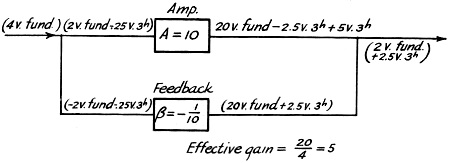
Fig. 2 - Noise reduction feedback loop.
"The usual type of nomenclature used in feedback amplifiers is given in Fig. 1.
It is to be found in numerous publications treating the subject.
"The reduction of gain caused by the feedback is 1/(1-Aβ).2 This
is also the reduction in noise and distortion produced in the stage.3
The characteristic with feedback approaches that of the feed- back or β circuit.
When, as in this article, β = -1/A, the factor 1/(1-Aβ) becomes 1/2.
The above factor is demonstrated below in obtaining the table given on page 47,
April QST:
"The actual case of the author's distortion example is shown in Fig. 2.
The 5-volt third harmonic produced in the amplifier is reduced one-half, to 2.5
volts, but not eliminated. If Aβ should be made as high as 15 to 20, then much
more reduction of distortion (1/16 and 1/21) would be obtained. I have no doubt
that the amplifier as described works very well, but there appears to be no foundation
for the desirable feedback ratio of 1/gain of stage."
1 Carter, "Inverse Feedback Applied to the Speech Amplifier for the
Amateur 'Phone Transmitter," QST, April, 1937.
2 When the feedback is negative, as is the case here, β is negative.
- Editor.
3 The amount of distortion fed back to the grid circuit is equal to β
times the resultant distortion in the plate circuit; i.e., the distortion remaining
in the output with feedback present. The resultant distortion is the algebraic sum
of the original distortion without feedback and the amplified feedback distortion.
Letting D = resultant distortion with feedback and d = original distortion without
feedback.
D = d + ADβ
Solving this for D,
D = d/(1-Aβ)
See Terman, "Feedback Amplifier Design," Electronics, January,1937. - Editor
Posted June 30, 2023
(updated from original post
on 10/17/2013)
|