August 1947 QST
 Table
of Contents Table
of Contents
Wax nostalgic about and learn from the history of early electronics. See articles
from
QST, published December 1915 - present (visit ARRL
for info). All copyrights hereby acknowledged.
|
 There is something about these proposed
shorthand circuit symbols that reminds me of the
IEEE digital logic symbols
using the distinctive shape (the traditional format) versus the newer rectangular
shape format (examples shown to the left). The set is quite extensive when all
the different flavors of combinatorial blocks - flip-flops, timers, counters, shift
registers, encoders, decoders, etc. - are included. My personal preference, you
might guess, is the original format with distinctive shapes. Although I do not do
a lot of digital work, it is easier for me to follow the signal flow and mentally
perform the logic operations with the distinctive shapes. But I digress. This article
from a 1947 issue of QST magazine introduces shorthand versions of analog schematic
symbols. I only need to go to the basic resistor, inductor, and capacitor symbols
to develop a bias against them. They do not seem to have been adopted widely by
the electronics community because I have seen a lot of schematics over the years
and do not recall ever seeing these used. However, it is worth posting them here
for the public to find in case someone out there does discover their use and wonders
what the heck is going on. Maybe you need to cut your teeth on the new symbols to
like them ... or be a lot more open to change than I am ;-) There is something about these proposed
shorthand circuit symbols that reminds me of the
IEEE digital logic symbols
using the distinctive shape (the traditional format) versus the newer rectangular
shape format (examples shown to the left). The set is quite extensive when all
the different flavors of combinatorial blocks - flip-flops, timers, counters, shift
registers, encoders, decoders, etc. - are included. My personal preference, you
might guess, is the original format with distinctive shapes. Although I do not do
a lot of digital work, it is easier for me to follow the signal flow and mentally
perform the logic operations with the distinctive shapes. But I digress. This article
from a 1947 issue of QST magazine introduces shorthand versions of analog schematic
symbols. I only need to go to the basic resistor, inductor, and capacitor symbols
to develop a bias against them. They do not seem to have been adopted widely by
the electronics community because I have seen a lot of schematics over the years
and do not recall ever seeing these used. However, it is worth posting them here
for the public to find in case someone out there does discover their use and wonders
what the heck is going on. Maybe you need to cut your teeth on the new symbols to
like them ... or be a lot more open to change than I am ;-)
Shameless sales pitch: I have custom sets of schematic symbols available for
both Visio and
Word.
Shorthand Circuit Symbols

Fig. 2 - Special forms are easily derived from the basic
symbols of Fig. 1.
The March, 1947, issue of Britain's Wireless World carries a story titled "Shorthand
Circuit Symbols," by A. W. Keen, that presents enough new ideas in representing
radio circuits to be of interest to all who deal with the beasties.
Although Mr. Keen points out that his "shorthand" method was developed only as
a faster technique for circuit representation and not as a replacement, there is
much to recommend it for general use. You can be the judge.
As Mr. Keen points out, there are four common components that must be represented
in radio circuits: resistance, inductance, capacity and vacuum tubes. These are
the ones, therefore, that should be simplified, since they occur so frequently.
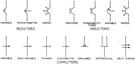
The first three basic circuit elements are simplified by reducing the present symbols
to a bare minimum, as shown in Fig. 1. That this "shorthand" presentation lacks
nothing in flexibility can be seen in Fig. 2, where various special forms of
the basic components are represented. Further, when these symbols are combined,
they still suffer nothing in clarity and certainly gain in simplicity, as is obvious
from Fig. 3.

Fig. 1- Simplified symbols for "shorthand" circuit representation.

Fig. 3 - Combinations of the basic components are a simple
matter, and they take less time to draw than the more conventional representations.

Fig. 4 - The "shorthand" vacuum-tube symbols are based on
the use of polygons whose sides equal the number of elements in the tube. Combination
tubes with common cathodes are easily represented.
Mr. Keen's symbol for a vacuum tube is quite ingenious. He points out that following
the various grids in multigrid tubes is an unpleasant process prone to error, and
that one must count the grids carefully before deciding what type of tube is being
represented. To eliminate all this, he represents a triode by a triangle, a tetrode
by a square, a pentode by a pentagon, and so on, as in Fig. 4. The side of
the polygon representing the cathode is made distinctive by superimposing a small
heater (resistance). The other elements of the tube then follow logically in a clockwise
direction around the figure, each element being represented by a side of the polygon.
Tubes like triode-pentodes and the like are represented by surrounding the triode
with the pentode and using the common cathode as the common side of the figure.

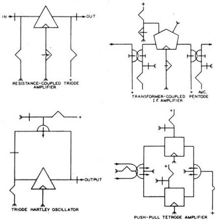
Fig. 5 - Familiar circuits represented by the "shorthand"
method.
Several other interesting points were developed in the "shorthand" system. Because
the symbols are small, the average wiring diagram is opened out and there are not
many "crossover" points. To avoid the "loop" used in QST diagrams, or the dot-no-dot
system adopted during the war - which often leads to confusion and error - the "shorthand"
method separates a four-wire junction into two separate junctions, and hence any
normal crossover of lines represents no connection. This makes for very simple construction
and considerably less chance of error. Chassis grounds, the usual common return,
are represented by a small "C" superimposed on the end of the wire, resulting in
what looks like a bird's claw, or the letter "E" (for "earth").
A few sample diagrams are shown in Fig. 5. - B. G.
|


