|
January 1947 Radio-Craft
 [Table of Contents] [Table of Contents]
Wax nostalgic about and learn from the history of early electronics.
See articles from Radio-Craft,
published 1929 - 1953. All copyrights are hereby acknowledged.
|
The January 1947 issue of
Radio-Craft magazine was dedicated to editor Hugo Gernsback to articles celebrating
the 40th anniversary of his personal friend Lee de Forest's invention of the
Audion amplifying vacuum tube. Click on the Table of Contents link to access many
of the other articles - all of which are very insightful into the many amazing activities
of Mr. de Forest. Many of the articles were written by friends and business
associates of him. The "radiophone" addresses here is actually one of the earliest
mobile phone, being interconnected by radio signals rather than a twisted pair of
wires. Take note of the "flame audion" mention, which believe it or not describes
de Forest's earliest experiments which used a pair of salted platinum plates
embedded in an actual flame. Yes, that actually constituted an amplifying element
for detecting RF signals. See "How the Audion Was Invented"
and "How Audions Were
Built" for details.
An Early Radiophone

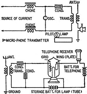
Fig. 1 - Transmitter and receiver schematics. These were typical
of early de Forest equipment. Oscillator symbol represents a carbon arc in its pot.
The telephone receiver shows strong influences from the 75-ohm line type, indeed
often used with radios of that period.

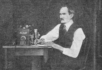
Fig. 2 - A photograph of de Forest at one of the instruments
described in this article.
<missing in original article>
Fig 3. - It was not possible to reproduce this figure. - Editor.

Fig. 4 - Close-up of receiving apparatus and tuning equipment.
The modern reader has difficulty in fully appreciating the impact of some of
de Forest's earlier discoveries on the technical world of the time. So obvious are
their effects today that it is difficult indeed to realize that they were by no
means so to the wireless authorities of the 1900's.
Readers can get a fair idea of how the radiophone was looked upon in those days
from the following article, reproduced verbatim from Modern Electrics,
August, 1908:
The new art of wireless telephony has advanced to such a stage that the U. S.
Navy has lately equipped 32 war vessels with complete sets. This point alone is
a guarantee of the practicability of the wireless telephone, as it is a well known
fact that the government does not adopt any apparatus until its utility has been
proven.
The sets were sold under a contract to hold unbroken communication up to a distance
of five miles regardless of fogs or atmospheric disturbances. This distance, however,
has been doubled several times, and the latest records show that a distance of 26
miles has been covered, the messages being picked up by the receiving end of a wireless
telegraph set which no doubt could have been farther extended by the use of the
special telephone receiving sets as employed with the telephone.
The fleet which sailed around the Horn to the Pacific was equipped with complete
sets. Admiral Evans could keep in constant communication with any of the ships -
directing the movements of the whole fleet from one point which may sound the death
knell of the old wig-wag system of signaling used for an indefinite period by the
navy.
The naval attaches are particularly proud of the fact that the U. S. navy is
the only one in the world utilizing this means of communication but already foreign
ambassadors are negotiating with the makers for like sets.
In operation the wireless telephone is very simple, and depends on the same principle
as telegraphy, that is, the generation of Hertzian waves that pass through space
186,000 miles per second. While the principle is the same, yet the actual working
is vastly different, as was soon realized by the numerous investigators who took
up the subject with the introduction of wireless telegraphy. In telegraphy the transformer
or transforming device is supplied by alternating current with periodic break or
direct current with mechanical break. In either case the emitted wave is periodic.
This, however, would not answer for wireless telephony, as the break would destroy
all properties of speech.
The problem now was to provide some means for generation of a continuous wave
current and impress thereon the modulations of the human voice which would possess
the same qualities when caught at the distant receiving end and reproduce the spoken
words.
The generation of such waves was made possible by the use of Duddell's arrangement,
which is identical with the wireless telephone of the day with the addition of a
few changes.
The circuits of the de Forest sending and receiving ends as shown in the May
issue are repeated here for sake of clearness.
The transmitting set consists of an ordinary are lamp (oscillator) burned in
the flame of an alcohol lamp from a 220-volt circuit, which sets up oscillations.
The latter flow through the condenser and primary of transformer, exciting the secondary,
which has one terminal leading to the ground through a telephone transmitter, and
aerial wire.
It can now be understood that the wave current in flowing through the transmitter
to the ground and aerial wire will be changed to the same proportion as the voice
which falls against the diaphragm of the transmitter. A certain portion of this
wave is caught by the antenna of the receiving end, which flows through the primary
of a transformer set to the same wave length; passing the secondary, it flows through
the capacity condensers to the "Audion"; here it produces a like change in the ionized
gases which changes the current from a local battery flowing through a telephone
receiver, resulting in the spoken words increased in sound to a large extent.
Here we have the complete de Forest system, which of course required a considerable
amount of ingenuity and work on the part of Dr. de Forest to bring the apparatus
to its present stage of perfection.
In the June issue of this magazine was described a "Flame Audion" which works
on the same theory as the one employed in wireless telephony. The "Audion" used
by de Forest is an ordinary incandescent lamp with a platinum grid and wing sealed
in a lamp bulb, as shown in the diagram. The "Flame Audion" has the platinum contacts
inserted in the flame impregnated with certain salts.
In Fig. 3 is shown a set designed for portable use, and is packed ready for transportation.
[It was not possible to reproduce this figure. - Editor].
With this set communication can be established in a short while, as portable
and easily handled aerial arrangements are being provided for this purpose. To the
left is the transmitter, consisting of the high tension coil placed in case with
telephone transmitter mounted on an arc lamp in the back. The telegraph key and
a device known as the "chopper," which resembles the ordinary buzzer, are shown
in the front. The "chopper" is inserted in the aerial wire, and when the key is
pressed operates the wireless telegraph apparatus, for calling, etc.
The complete receiving set is shown in Fig. 4. Here we have the "pancake" syntonizer
on top, adjustable condenser, tuning arrangement, and reserve "audion" for use in
emergency.
In Fig. 2 is shown Dr. de Forest at the instrument, the audion is seen between
his hands.
Posted August 24, 2020
|


