|
October 1935 Radio-Craft
 [Table of Contents] [Table of Contents]
Wax nostalgic about and learn from the history of early electronics.
See articles from Radio-Craft,
published 1929 - 1953. All copyrights are hereby acknowledged.
|
The advent of metal-encapsulated
vacuum tubes was supposed to be the death knell for traditional glass tubes. This
1935 article from Radio-Craft spelled out the many virtues of "metal" tube
and how in short order their superiority would obviate the need - even desire -
for "glass" tubes. I'll let you read the article for the details, but want to make
note of an evidently archaic term used that could potentially be really popular
in today's manufacturing world if duly resurrected - "quantiquality" (aka "quanti-quality"
or "quanti quality"). The connotation is a process of high quantity in conjunction
with high quality. The only references I could easily find to quantiquality was
from late-19th-century newspaper archives. If sometime within the next few years
you start seeing some form of quantiquality appear in marketing copy and scholarly
papers, remember that you heard it here first!
An Inside Story About Metal Tubes

Fig. 1 - Table I lists the above details.
Interesting details concerning the all-metal tube; also, recently-introduced,
associated types are described.
R. D. Washburne
Metal tubes - being more compact, inherently strong in structure and having many
manufacturing advantages over glass tubes - fulfill an urgent need in the field
of applied electronics.
As the artist has expertly illustrated, Fig. B., the glass tube design that
has held sway for the last 28 years at last has succumbed to the modern demand for
"quantiquality" (a word coined by Sachs which aptly typifies the modern demand for
greater production and closer tolerances)!

Table I - Element description for Figure 1.

Fig. A - Left, metal-tube exterior; center, "X-ray eye"
view; right, cross-section. (G.E.)

Fig. D - Metal-glass tube.
The Glass Prototype
The case against glass tubes is a strong one, but only a few important points
will be mentioned.
That there is little difference between the elements inside the glass and the
metal envelopes is evident by reference to Fig. F. This view shows that a great
amount of material required in order to secure rigidity within the necessarily large
glass bulb, is not required in a metal tube.
It is necessary to coat the glass bulb with a graphite preparation in order to
prevent the collection of potential charges on the bulbs, especially at the higher
radio frequencies. The metal envelope eliminates this fault, permitting perfectly
satisfactory operation right on down to below 5 meters! (See the article, "An 18 Metal Tube All-Wave Superhet," in this issue.)
The metal tube structural requirements previously mentioned, and some of those
hinted at, will be evident by reference to Fig. 1, which illustrates a typical
screen-grid tube; a description is given in Table 1.
(Additional construction details appeared in the article, "Now - Metal Tubes," in the
June, 1935 issue of Radio-Craft.)

Fig. B - Going-going - - -!

Fig. C - "Metal-spray" tube.

Fig. E - Glass-"metal" tube.
At the same time, the metal envelope is much superior and more convenient in
its function as a metal shield and in reducing inter-electrode capacity than is
the skin-tight shield required in a good glass-tube arrangement. Present circuit
practice demands that the grid-to-plate capacity of a typical screen-grid tube be
approximately 0.01-mmf., or less. The metal tube reaches this tolerance with little
difficulty.
X-Ray Examination
X-ray eyes would- be required to see "through" the opaque metal tube. Therefore,
what is more logical than that the X-ray should be used in checking the internal
arrangement of the elements in defective tubes? This procedure eliminates the need
for an expensive wrecking process in order to check the malformation of the elements
within the normal number of tube rejects. The internal arrangement of the elements
(in screen-grid arrangement) as thus disclosed by X-ray is illustrated in the central
view in Fig. A (and the cover illustration), and may be compared with the exterior
and cross-section views at the left and right. X-ray views of the representative
types appear in Fig. G. This photograph and the preceding X-ray view were taken
by the General Electric Company especially for Radio-Craft; (they are interesting
examples of the advanced X-ray photography technique which makes it possible to
obtain such excellent "separation" of the various metal elements within the steel
jacket).

Fig. G - G.E. X-ray photos of metal tubes.
"Other" Metal Tubes
An article discussing the present status of metal tubes would be incomplete without
mention of several new technical developments in related types. The consumer should
acquaint himself with the following facts in order that due justice may be given
to all concerned.
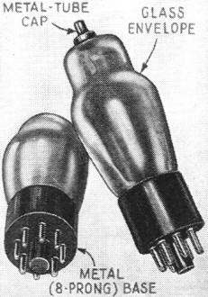
A Canadian manufacturer, Rogers Radio Tubes, Ltd., has just introduced a type
of tube which at first glance might be confused with the steel jacket variety. However,
as shown in Fig. C, the envelope is of glass, and only the "octal" (8 prong)
base is of the metal type. The glass bulb is given a metal coating; from this process
is derived the term -"metal-spray" tube. The metal-spray tube is completely shielded
from top to the bottom of the base; it is furnished in dual-purpose types. The new
interior construction of the tube includes the cementing of the grid rod to the
ceramic top-support, together with expanding and sealing of the cathode tubing to
this ceramic support.
This eliminates the possibility of noise due to vibration, as well as the possibility
of hum from the cathode tubing or poor emission from the cathode coating.
A second variation has been brought out by Triad Manufacturing Company, Inc.,
and is illustrated in Fig. D. These metal-glass tubes are known as the MG series
and are not all-metal, there being a glass inner sleeve which is used for maintaining
the vacuum.

Fig. F - Illustrating metal vs. glass tube type.
The MG series at present, includes the following types: 5Z4MG, 6A8MG, 6C5MG,
6D5MG, 6F6MG, 6H6MG. 6F7MG, 6K7MG; the characteristics of these tubes are said to
parallel those of all-metal construction. There is available in addition the following
types, for use in A.C.-D.C. sets: 25Z5MG and 43MG. with characteristics similar
to those of the types 25Z5 and 43 tubes; there is also available a type 50A2MG tube,
which is a ballast tube in a metal shield with a tap to supply two No. 40 pilot
lights in series, and type 50B2MG, similar to the 50A2MG except that it is tapped
to supply only a single No. 40 pilot lamp. Both ballast tubes have an over-all drop
of 50 V.
The tubes in the MG series incorporate standard octal bases.
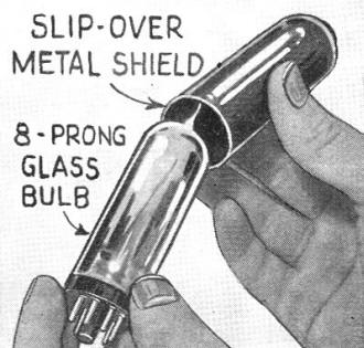
Finally, there is the type of tube which, while it incorporates an octal or 8-prong
base, utilizes a glass envelope and depends for its shielding upon an external shield.
This glass-"metal" tube described in the August, 1935 issue of Radio-Craft as item
No. 754, is illustrated here in Fig. E. The characteristics are said to approximate
those in the regular metal series. The latest step towards securing identical characteristics
has been to use a skin-tight shield of improved design. This shield is illustrated
in the Latest in Radio Department of the October issue as item No. 820. The glass-"metal"
series, identified by the suffix letter G, is a product of Arcturus Radio Tube Co.
Conclusion
It is interesting to speculate on how many manufacturers of test equipment may
have provided switches to take care of the unavoidable discrepancies that so far
have arisen in the "standardization" process in connection with metal tubes.
We refer specifically to the types 6F5 and 5Z4 tubes.
Metal 6F5 is a high-mu triode, with its plate connected to No.4 terminal instead
of the No. 3 terminal utilized for plate connection in the other amplifier tubes
in the metal series. This connection to No. 4 terminal eliminated undesirable circuit
regeneration.

Fig. 2 - This metal cap completes the shielding.
Metal 5Z4 is a full-wave rectifier about equivalent to the glass 80; therefore,
its filament potential is 5 V., against 6.3 for the remaining tubes in the metal
series. To prevent damage to the 5 V. filament of the rectifier if plugged into
one of the 6.3 V. sockets, or to the plates of the 6.3 V. tubes due to high voltage
if plugged into the rectifier socket, the rectifier filament terminal wires are
connected instead to terminals Nos. 2 and 8, instead of Nos. 2 and 7 like the remaining
tubes in the metal series. (We wonder how many technicians are going to cuss the
circuit limitations imposed by reason of the 5Z4 filament being tied to the high-voltage
side of the rectifier output?)
Service Men and experimenters who wish to revamp existing equipment in order
to properly test the metal tubes should note that some analyzers have the No. 1
or ground terminal of the octal socket grounded to the metal mountings and the wiring
- at the same time, the No.8 terminal is grounded. This puts the tube shield at
the rectifier cathode potential - that is, 350 V., in some instances! (An army mule
can't beat the kick you'd get from that jolt!) Just remember, then, to isolate the
wiring to terminals 1 and 8.
Heating of the metal tubes, as compared with the glass type, is a popular topic
for discussion these days. Do the metal tubes run hotter than the glass ones of
equivalent type? If they do, and the rise in temperature is due to better conduction
by the steel envelope, is this an indication that the tube will perform better because
the internal elements are being kept more cool? These and other questions of this
nature are still to be answered; it is of exceptional interest that an article discussing
the subject will appear in a forthcoming issue of Radio-Craft.
Some off-hand claims have been made that the metal tubes are less sensitive and
more noisy than the glass predecessors. On the contrary, comparative tests between
receivers utilizing similar sets each properly designed, one for the metal tubes
and the other for the glass prototypes, prove that the metal tubes are more sensitive
and less noisy than glass tubes!
Finally. there remains the question of whether the metal tubes will work at very
high frequencies. Well. the writer is in the position of having heard a commercial
metal-tube set (described elsewhere in this issue) operating on 4 1/2 and 5 meters!
It functioned with far greater tone quality, and far less static at 5 meters than
did the same set at the broadcast wavelengths!
It seems, however. that in some circuits the shield of the metal tube when operated
at ultra-high frequencies may exhibit hand capacity. Whether this is due to lack
of conductivity of the Swedish-iron shield, to close proximity of the internal elements,
or to some other reason has not as yet been definitely determined.
It is even possible that the control-grid terminal atop the tube, in some high-gain
circuits may present sufficient area to cause inter-tube feedback and circuit oscillation
or undue regeneration. An expedient to obviate this fault is the use of a top-cap
shield, constructed as illustrated in Fig. 2.
Definitely, metal tubes are here to stay. Therefore, the radio man might just
as well start right now to absorb every available bit of technical data relating
to them.
Posted March 30, 2022
(updated from original post on 10/26/2015)
|


