|
December 1936 Radio-Craft
 [Table of Contents] [Table of Contents]
Wax nostalgic about and learn from the history of early electronics.
See articles from Radio-Craft,
published 1929 - 1953. All copyrights are hereby acknowledged.
|
My first thought when seeing
the cover for this December 1936 edition of Radio-Craft magazine was that
it was an April Fools gag, but it turns out the "Hat" being worn by the radio receiver's
designer is a loop antenna for AM reception. In a way it is the opposite of a tinfoil
hat in that this headgear invites electromagnetic energy around the wearer's head
rather than shielding it. Back in 1936, being seen in public donning a contraption
like this radio would have been akin to wearing
Google Glass (a failed
concept) a few years ago - you'd be a superhero to fellow nerds, and just be confirming
your otherworldly nerd status to non-nerds. Note the very nicely done drawings.
How to Make the World's Smallest 3-Tube Radio Set

Fig. A - The tiny chassis removed from its cabinet. Note
the size.
By Arthur C. Miller
This little receiver - a typical experimenter's set - will attract the interest
of radio men everywhere. Tested inside Radio-Craft offices (the 11th floor of an
all-steel building in lower Manhattan) the local stations were received without
the least difficulty!
Once again Radio-Craft presents a "world-beater" in small-space radio equipment.
In September, 1935, Radio-Craft was described the world's smallest 1-tube set that
first introduced midget tubes to the American radio man; the article aroused international
comment! By a clever combination of midget parts, including batteries, tubes, condensers,
etc., the author has made a practical, proportionately-small, 3-tube "world-beater"
radio receiving set!
When using this "Belt-Radio" the wearer is quite unmindful that the latest news
or dance music is coming from an ultra-midget receiver which is actually being worn
on the belt! And it takes only a minute to put the whole equipment on-and less to
take it off! Technical men will better appreciate the amazing sensitivity of this
tiny set, with its "hat" antenna, on being told that the writer has had no difficulty
in receiving WCAU (Philadelphia) and WHAM (Rochester), on the 5th floor of a 14-story
all-steel building in mid-Manhattan! The circuit is fundamentally a regenerative
detector followed by 2 stages of audio amplification. A closer inspection, though,
will reveal that the gridleak-and-condenser combination is arranged in an unusual
manner-across the tuning coil and in series with the variable condenser (C1). This
was found to give far better results with a closed antenna circuit of the type used
than the more conventional method, and also enabled absolute stability to be obtained
with the minimum of bypassing and shielding. In fact no shielding at all was used.
Finally, there is not the slightest trace of hand-capacity effect to upset the tuning
on the 200 to 550 meter range (broadcast band).

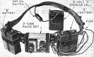
Fig. B - The complete set, ready for operation. The "A"
battery is a storage cell; the 45 V. "B" batteries are the new midget size. Note
the fuse.
Fig. D - Here is the picture wiring diagram for those experimenters
who prefer this system.

Fig. E - The author "harnessed up" - and enjoying a musical
selection.

There are one or two important points to remember. The loop aerial was designed
to fit 'round the head because that was found to be the only position in which it
gave satisfactory results. On the back it was too close to the body and when the
receiver was in its most sensitive state (just before circuit oscillation) every
movement of the body upset tuning and regeneration. But, unfortunately, there is
one disadvantage in having the aerial placed that way. The 4-ft. cable connecting
it with the receiver acts as a capacity and restricts the tuning range of the set.
What the author did was to choose the most powerful local (New York) transmitter
(which happened to be WOR, Carteret, N. J.) and wind the number of turns on the
loop which enabled him to tune to that frequency (710 kc.) . Besides WOR he could
receive WLW (700 kc.) in Cincinnati, WEAF (660 kc.) in New York, and in the other
direction WJZ (760 kc.) in Bound Brook, N. J. Of course tapping the coil will help
considerably to broaden the tuning range.

Fig. C - The positions of the parts can be seen here. The
tube sockets had to be filed down to fit on sub-panel. The special tuning condenser
is seen behind the sockets.
Building the set is quite simple. A thin Bakelite panel is used (3/16-in. thick,
and 3 1/2 x 2 1/2 ins. wide) on which are mounted the midget tuning condenser and
the 15,000-ohm, wire-wound, regeneration and volume control. The tiny chassis is
also made from Bakelite of the same thickness, on which are mounted the 3 sockets
to hold the tiny tubes (distributed, like the sockets, in the U.S. by Wholesale
Radio Service Co.). The sockets will have to be cut down to fit the chassis which
measures only 2 3/8 x 3/4-in. wide. It may be well to mention here the importance
of using only the specified parts. They are the smallest known and any larger parts
will, of course, make it impossible for the reader to keep the set at its present
small dimensions. A good suggestion, too, would be o advise the use of a small soldering
iron! (The kind the author recommends is not larger than an electric stencil pencil.)
The loop aerial is wound on a cardboard disc 13 ins. in dia. Litz wire is used
and 22 turns are interlaced around the 9 ribs. (Note that an uneven number must
be used.) A tap is made at the 17th turn from the start, This is the" A-" lead to
the set. A 3-way mike plug and connector separates the loop from the receiver so
as to facilitate putting the equipment on and taking it off. The completed set and
the two 45-V. batteries are mounted with black elastic bands (3/4-in. wide) onto
an ordinary leather belt. Tap one of the 45-V. units at 22 1/2 V. Due to the extremely
low "B" drain, about 2 1/2 ma., the two 45-V. batteries should give at least 100
hours of service. This is calculated on the daily use of the set for about 3 continuous
hours.
A liquid unspillable storage cell supplies the 2 V. for the filaments. This tiny
"battery" (as most people prefer to call it) should last from 7 to 10 hours before
needing to be recharged. It is sold with an oiled silk bag and fits in the hip pocket.
Note: the grid prong of the tiny tubes is larger than the remaining prongs. As
L, in Fig. 2, you may use either the "hat" loop, or a small, experimental coil
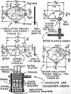
when using a ground and outside antenna (for DX). The writer imported several of
the ultra-small condensers detailed, for constructors who wish to make them, in
Fig. 3.
The "secret," if you want to call it that, of success with this tiny set is in
the high degree of A.F. and R.F. amplification secured.
|

Fig. 1 - The schematic circuit including values of all parts.
Note the grid leak and condenser.

Fig. 2 - Alternative wiring of the grid leak.

Fig. 4 - The "hat" details.
|

List of Parts

Fig. 3 - The special tuning condenser is made according
to these specifications. Two separators are used between stator plates.
|
Posted May 23, 2022
(updated from original post
on 1/12/2016)
|


