|
June 1932 Radio-Craft
 [Table
of Contents] [Table
of Contents]
Wax nostalgic about and learn from the history of early electronics.
See articles from Radio-Craft,
published 1929 - 1953. All copyrights are hereby acknowledged.
|
In no way do I advocate going back
to the "old ways" for manufacturing electronic components, but I do admire and like
to give credit to the people who used to perform the tedious procedure of building
vacuum tubes, hand-wire chassis assemblies, circuit boards, etc. This 1932 issue
of Radio-Craft magazine article is good example. The process required being
able to sit or stand at the same work station and perform the same range of operations
day after day, often for years on end. Of course at the time, automation processes
were not what they are today and machinery needed to be driven by mechanical means
using motors, solenoids, and limit switches. That made employing people more financially
rewarding than using a machine. You can find details on the algorithms and methodology
for designing those contraptions in older engineering handbooks. It is an amazing
sight to to tour a WWII vintage battleship and look at the hardware that stabilized
and steered the cannons without an electronic computer in sight.
Making Modern Tubes
 By Arthur H. Lynch in collaboration with Edward Caron By Arthur H. Lynch in collaboration with Edward Caron
(1) This is an automatic grid winding machine. Two heavy support wires are run
through a revolving head - at the extreme left of the picture. As these two support
wires revolve, being driven by the motor which operates the revolving head, they
pick up a fine wire which is run at right angles to the support wires and is equally
spaced along the support wires. The spacing is automatically controlled for any
particular type of tube for which the grids are to be used. This makes one long
grid, the entire length of the support wires.

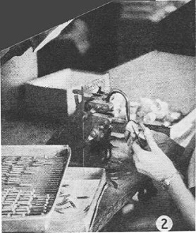
(2) Cage Assembly - The operator is using a foot-controlled electric welding
machine. The upper arm of the welding machine makes contact with the metal elements
which the operator is holding.

(3) Cathode Assembly - Here the operator is shown placing the special alloy filament
wire into the Isolantite insulating sleeves.

(4) Cathode Spraying - After the operation shown in Figure No. 3, groups of the
individual cathodes are placed in a spraying hood and given a coating of prepared
chemicals by means of the spray gun which the operator holds in her right hand.
The performance and the ultimate life of the heater-type tube depends, to a very
large degree, upon the uniformity of the spraying mixture itself as well as the
uniformity with which it s applied.
This is one of the most important operations of the cathode.

(5) Hydrogen Furnace - All of the small parts which have been shown in the foregoing
photographs, as well as any other metal which is contained inside the glass envelope
of the tube, are placed in this furnace before being assembled.

(6) Automatic Flare Machine - Long lengths of glass tubing are placed in the
revolving chucks which are shown at the top of this machine. These chucks feed the
glass tube, at a predetermined, desired length, into a number of gas flames. There
are eight sets of gas flames which the tube passes through from the time the operation
starts until the flare is finished. Each different position is accompanied by an
increase of temperature of the flame acting upon the glass tubing as the process
develops. At the position shown directly before the operator is a revolving steel
flare cutting disc.

(7) Stem Machine - The operation shown in this picture is worked out in six different
positions which are automatically rotated by the machine. The result is the inserting
of the necessary lead wires which connect the elements of the tube to the prongs
of the tube base, which in turn goes into the socket of the radio receiver. The
small glass tube, which is shown in the operators hands, is used in a later operation
for evacuating the entire tube. It joins the flare at a point where the lead wires
are sealed into the glass.

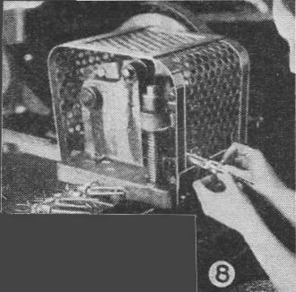
(8) Automatic Stem Bender - Stems taken from the machine shown in Figure 7 are
then placed in this device which is controlled by a foot-operated clutch. When this
machine is operated all of the lead wires are cut to the proper length.

9) Mount Assembly - The operator in this picture is using a machine similar to
the one shown in Figure No.2. The difference lies in the fact that all of the assembly
which has been finished by the process shown in Figure No.2 is now joined to the
rest of the elements, making a complete "Mount," ready for inserting into the glass
envelope or bulb.
After the "Mount" is completed, the unit goes to the sealing-in" machine.

(10) Mount Assembly - The machine here is somewhat similar to the flare-making
machine in that the operation includes passing the elements for the tube through
a number of gas fires of gradually increasing temperatures.

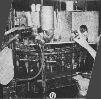
(11) Exhaust and Sealing Machine - The entire tube assembly is run through this
machine in such a manner as to drive off all of the gases and pump them out along
with all the air in the bulb. The heavy coil of wire directly above the heavy insulated
lead wires, is a high frequency coil, used for heating the elements within the tube,
while it is being evacuated. The heat of the elements is produced purely by the
inductive effect of the high frequency current passing through the coil. A "getter"
explodes, giving a "silvery" appearance.

(12) Automatic Basing Machine - Here, the completely evacuated and sealed assembly,
taken from the former operation, is attached to the base. The base is already fitted
with the requisite number of tubular metal prongs. The lead wires are put through
these tubular prongs, by the operator, before the tube and the base are placed in
the basing machine. The base, itself, is filled with a specially prepared cement.
These assembled units are then put through a circular oven, which is held at a constant
temperature.

(13) Aging Rack - This highly interesting section of the production line indicates,
by means of the banks of ordinary incandescent lamps, just exactly the condition
of each tube as it comes through production. The finished vacuum tubes are placed
in sockets which are connected to normal operating voltages. The current is then
turned on and each tube has to be aged for a given period at specified voltages.
If there is a short circuit between a plate and grid of one of the tubes, one of
the lights in the bank to which that particular tube is connected indicates that
fact to the oper-ator. Other lights detect other troubles. This is true of any other
flaws which might take place in the tube and the operator is therefore able to throw
out those that are faulty.

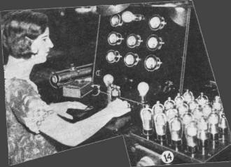
(14) Test Table - A table, of this character, is at the end of each production
line. It is fitted with nine delicate meters and is used to measure ten different
characteristics of each tube. These test tables are of the very latest design and
are the work of the Triad Engineering Staff.

(15) Packing - All of the highly developed Engineering work in a modern tube
plant can be knocked into a "Cocked Hat" if the tubes are not satisfactorily packed.
After shipping millions of tubes to all parts of the world the Triad Company has
standardized on a system of wrapping.
* Plant Superintendent, Triad Television Mfg. Co.
|


