|
August 1944 Radio-Craft
 [Table
of Contents] [Table
of Contents]
Wax nostalgic about and learn from the history of early electronics.
See articles from Radio-Craft,
published 1929 - 1953. All copyrights are hereby acknowledged.
|

National Union Type 6324 Radial Beam-Switching Commutator Tube
(Lamps &
Tubes photo)
Signal multiplexing was originally performed using a rotating mechanical device
with commutator contacts. Such a contraption suffered from a number of limitations
including contact wear, noise, speed, size and weight. Probably the most limiting
were contact wear and switching speed. Bulk could be accommodated because back then
everything was bulky. Standard vacuum tube switches were eventually used to build
multiple (n) input / multiple (m) output switching circuits, but the space needed
to contain them grew exponentially with the n x m matrix. Bell Telephone Systems,
which played a huge part in the advancement of primarily wired communications systems,
developed a "radial-beam tube" that used a magnetic field to steer the electron
flow between opposing sets of anodes and cathodes. Steering circuits controlled
the position of the electron beam within the tube. Since there were no moving parts,
many of the drawbacks of mechanical systems were eliminated.
A Radial-Beam Tube
New Development is an Electronic Commutator
By I. Queen
All illustrations courtesy of Bell System Technical Journal

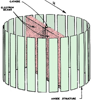
Fig. 1 - Drawing shows the focused beams. Rotation of these
beams by a magnetic field is the tube's secret of operation.

Fig. 2 - How the focused beam looks (above and below). The
electron paths were made luminescent by putting a small amount of gas into the tube.


Fig. 4 - Internal construction detail.
An entirely new type of tube with unusual possibilities has been developed and
is already in operation in New York City, in a multiplex signaling system. This
radial beam electron tube is remarkably simple in construction, requires no focusing
arrangement, is small, works on low voltages and has high efficiency. It is used
as an electronic commutator device and has recently been described in the Bell System
Technical Journal by A. M. Skellett.
The cathode of this tube is held vertically and is surrounded by a cylindrical
anode structure, as shown in Fig. 1. If each anode is at the same positive
voltage with respect to the cathode, the anode current will, of course, be equally
distributed among them, and each anode will receive approximately only 3% of the
total cathode emission.
If a magnetic field (such as shown by the Harrow) is applied, the electron beam
will be directed in only two diametrically opposite directions (Fig. 1), parallel
to the applied magnetic field. If the uniform magnetic field were made to revolve,
so would the two beams, so that such a field could serve not only for focusing but
to provide rotation. In this application the two beams will contain approximately
90% of the cathode current!
The action of the beam is well shown in Fig. 2. For these photos the cathode
was actively coated in only two opposite spots. Note how the electron beam twists
in following the applied magnetic field.
A convenient rotating magnetic field is furnished by the stator of a two-pole
poly-phase A.C. motor. The tube is simply inserted into this stator in place of
the usual armature. An unwound stator of this type is shown alongside an experimental
tube in Fig. 3. The loss in a typical stator is under three watts, making the
entire set-up highly efficient.
The tube in Fig. 3 is constructed with 30 anode elements. Each element is
really a pentode tube, containing a control grid, screen, suppressor grid, along
its path. Fig. 4 shows the construction. Note that only one beam is emitted,
the other being suppressed.

Fig. 3 - The radial beam tube and its field magnet.
Suppression of one of the beams is accomplished in several ways. At any instant
the anodes on one side of the tube may be maintained positive and on the other side
negative, this polarity rotating with the magnetic field. It may also be done by
means of the suppressors. Still another method is to use an odd number of anode
elements. Then when the beam falls on an element on one side it will fall between
two elements on the other.
The maximum cyclic speed is approximately 10,000 per second. Since no mechanical
wear results and no inertia is present, this tube makes an ideal rotating commutator.
An early system of multiplex telegraphy used a mechanical rotating commutator
which switched in each communication channel for a small portion of the total time.
This system proved impractical because of mechanical difficulties. The present tube
will, of course, eliminate these difficulties. Incidentally, this type of communication
does not require the elaborate filters of the carrier system, now in wide use.
Two tubes of the radial beam type have been operated successfully in New York
for experimental signaling. A neon tube in the anode circuit of each element was
used as indicator. The only amplification provided was that of the tube itself!
Both transmitting and receiving tubes were connected to the same source of 60 cycle
A.C. so that automatic synchronism of corresponding anodes was obtained. Much will
probably be heard of this tube in the near future.
Posted May 2, 2023
(updated from original
post on 8/21/2014)
|


