|
February 1964 Radio-Electronics
 [Table of Contents] [Table of Contents]
Wax nostalgic about and learn from the history of early electronics.
See articles from Radio-Electronics,
published 1930-1988. All copyrights hereby acknowledged.
|
The bridged-T filter
is a quick-and-dirty construct used to notch out a specific frequency that is
interfering with a desirable frequency or band of frequencies. It is a resonant
LC (inductor-capacitor) circuit consisting of a single inductor "bridging" a
pair of series capacitors having a resistor to ground between them, or, if
preferred, a capacitor bridging one or two inductors. A convenient
nomogram (aka nomograph) is provided by the author in this 1964
Radio-Electronics magazine article for quickly selecting values,
which was a very popular design aid in the pre-calculator era. A slide rule
could be used to calculate a range of values when only a single variable was in
play, but juggling more than one variable (component value) was greatly aided by
a multivariable nomograph. Truth is nomographs can still be a valuable design
tool. Of course there is software (usually very costly) with optimizer
algorithms where you input a circuit architecture, then specify a desired output
and let the computer settle on values. Really high end optimizers accept
parameters for preferred "Q," component tolerances, and acceptable output range
based on both component tolerances and temperature range.
The Bridged-T
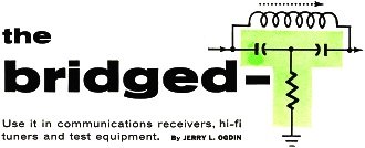
Use it in communications receivers, hi-fi tuners and test equipment.
By Jerry L. Ogdin
Little has been published on bridged-T (or T-notch) filters. This useful breed
of circuit can attenuate or "notch out" an undesired frequency, as in harmonic-distortion
analyzers and communications receivers. Used in a feedback amplifier, it can also
select a "peak" or a desired frequency while rejecting all others.
A few years ago, the bridged-T filter gained new popularity in several amateur
and communication receivers. There, the purpose was to attenuate an interfering
carrier. (The bridged-T works from audio to higher radio frequencies.)
Fig. 1-a shows a typical bridged-T filter, designed for 455 kc. The inductor
and capacitors resonate at the frequency to be notched out. Shunt resistor R has
a unique function: it determines the amount of attenuation in the notch. Usually,
with the optimum value of R, the notch depth is about 45 db. (That is, the output
at the notch frequency is about 45 db down from the input voltage.) R has an optimum
value for maximum rejection, and any other value will give less notch depth and
more bandwidth.
The bandwidth of the bridged-T filter depends also on the Q of the inductor.
Fig. 1-b shows typical bandwidth curves for two inductors, one having a Q of 1,
the other a Q of 100. The higher the Q, the narrower the bandwidth and the tighter
the skirt selectivity.
Fig. 1-c is the same circuit as Fig. 1-a, drawn in equivalent-circuit form. Resistor
Rs is not an actual resistor; it represents the ac resistance of the
coil. Once this is known, the value of the shunt resistor of the network can be
calculated.

Fig. 1 - Bridged-T for 455 kc. (b) Typical curve for high-Q
and low-Q coils. (c) Equivalent circuit of (a) showing Rs,
coil's resistive component.
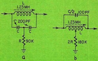
Fig. 2 - Two different forms of the bridged-T filter.
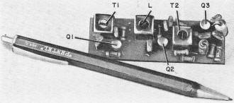
The i.f. amplifier of Fig. 7. It's 3 7/8 inches long by 7/8 inch
wide.
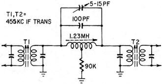
Fig. 3 - A simple i.f. filter for notching out interference.
The whole circuit should be substituted for one i.f. transformer. If only one side
of each transformer in receiver is tuned, T1 and T2 should both have tuned side
as primary.
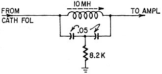
Fig. 4 - A 10-kc "whistle filter" for hi-fi AM tuners. Use
it from low impedance to high impedance.
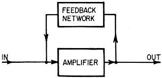
Fig. 5 - "Classical" functional diagram of feedback amplifier.
Here, amplifier has 180°-phase shift, feedback network 0°.
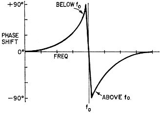
Fig. 6 - Phase shift diagram for bridged-T. Note sudden, rapid
change from +90° through 0 to -90°, which makes filter very selective.
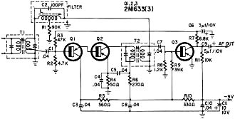
Fig. 7 - Practical high-selectivity if amplifier. Bridged-T network
provides 100% negative feedback at all frequencies except 455 kc.
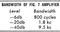
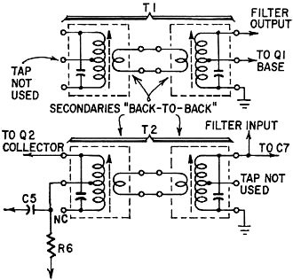
Fig. 8 - How to wire four single-tuned if transformers for use
as T1 and T2. See parts list.
The formula for resonance in this circuit is
fC = 1/2π √(2/LC)
and, for maximum null at the frequency of interest,
Rs = Xc2/Rs
where Rs = XL/Q.
The nomogram was developed to simplify the calculation of bridged-T
filters. Easy to use, it makes the task of "turning the mathematical crank" to get
an answer a lot simpler. First select a coil. Either calculate, measure, read out
of a catalog or guess the inductance, and enter this information on the L scale.
Next, set the frequency of operation on the f scale. Using a straightedge, connect
the two points just marked, and read out the value of the capacitors required for
resonance on the C scale.
If the Q of the coil is known, calculate the value of Rs according
to the formula given above. Enter this on the Rs scale. Connect the point
on the Rs scale and the point last crossed on the unmarked line between
the L and R scales. After connecting these two points, read the R column to find
the approximate value of the shunt resistor.
It's rare that the junk box will yield a coil of known Q. In this case, construct
the filter, insert a potentiometer, and "tune" for a null. It is good to do this
even when the resistor value has been calculated, because according to Murphy's
law, "if any error can possibly creep into any calculation, it will invariably do
so."
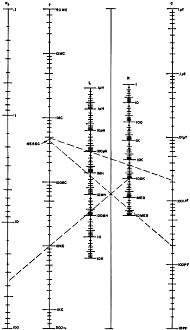
To Use the Bridged-T Nomo
Mark off the inductance of the coil on the l scale, and set the
intended frequency of operation on the f scale. With a straightedge, connect those
two points. The line will intersect the C scale at the capacitance required to resonate
with the inductor at f.
Knowing the frequency and selecting a suitable capacitance, you
can find the proper inductance value in the same way.
If you know the Q of the coil, calculate Rs according
to the formula Rs = XL/Q. Mark this value on the Rs
scale, and now draw a line from this point to the point where the line you drew
to find l or C intersects the ungraduated line between the L and R scales. Extend
the Rs line beyond that point and into the R scale. Read off the approximate
value of shunt resistor R from the R scale.
The example shown on the nomogram is for the filter of Fig. 1-a.
The filters of Fig. 2-a and 2-b are electrically identical. If the inductor chosen
has a center tap, use it. In that case, the single capacitor has one-half the value
determined in the nomogram, and the value of the shunt resistor is doubled (assuming
no change in the value of the inductor).
Using the Filter
A bridged- T filter may be connected with either side as an input. The shunt
resistor is connected to a point which is at ac ground. The impedance of the filter
presented to an input source is approximately equal to the shunt resistor, and the
source should have an impedance of less than that value. The output should be loaded
lightly - that is. look into a high impedance.
A simple filter system that can be used with nearly any 455-kc i.f. amplifier
is shown in Fig. 3. The variable capacitor is used to tune the notch over a small
range to an interfering carrier. The 90,000-ohm resistor may be replaced with one
of 22,000 ohms in series with a 75,000-ohm potentiometer. This provides variable
notch depth and selectivity.
Another use for the T-notch is in high-fidelity AM tuners, where 10-kc heterodyne
whistles are often disconcerting. The circuit of Fig. 4 can be used to attenuate
10 kc, Of course, the values shown on the schematic are only examples, and may be
changed to suit the junk box by using the nomogram.
Reversing the Notch
Although the bridged-T is very good for rejection filtering, it cannot be directly
wired for use in bandpass circuits. However, consider the basic voltage amplifier
with negative feedback (Fig. 5). If, classical theory has it, we want to eliminate
some frequency, we feed back that same frequency 180° out of phase with the input
and the frequency cancels out. Conversely, if we want to amplify only one frequency,
we feed back all except the desired frequency.
However, we must know the phase shift through the filter itself. Fig. 6 shows
it at various frequencies. Near the center (resonant) frequency, the phase shifts
rather violently from +90° to -90°, passing through the point of zero phase
shift at the resonant frequency. Therefore, for a tuned bridged-T, the phase shift
can be assumed to be zero.
Practical Circuitry
The circuit of Fig. 7 is the result of research into an inexpensive selective
i.f. amplifier. The bandwidth of the amplifier at various levels is shown in the
table, but can be spread by reducing the value of filter resistor R1.
Parts List
R1 - 90,000 ohms (see text)
R2 - 4,700 ohms
R3 - 47,000 ohms
R4 -
50 ohms (use 47- or 51-ohm resistor)
R5 - 560 ohms
R6 - 270 ohms
R7
- 6,800 ohms
R8 - 1,200 ohms
R9 - 39,000 ohms
R10 - 330 ohms
R11
- 10,000 ohms
All resistors T/2 watt, 10%
C1, C3, C4, C5, C7, C8,
C10 - 0.04 μdisc ceramic
C2-100 pf ceramic or silver mica
C6 - 3 μf,
10-volt electrolytic
C9 - 5 μf, 1O-volt electrolytic
C11 - 10 μf 10
volt electrolytic
L - 1.23 mh slug-tuned coil, center-tapped. (If center-tapped
coil not available, use two 200-pf capacitors instead of C4, as per Fig. 2-a.)
Q1, Q2, Q3 - 2N1633 or similar
T1 - 455-kc double-tuned transistor i.f.
transformer. Secondary tap 1,500 ohms
T2 - 455-kc transistor i.f. transformer,
5,000-ohm secondary.
[The author states that these double-tuned i.f. transformers are not widely advertised
or listed in catalogs but many distributors stock them as a kit of replacement transformers
for Japanese radios. Check your dealer's counter display cards or bargain counter.
If they are not available, use two Stancor RTC-8671 or J. W. Miller 9-C1 transformers
connected back to back for T1 and T2. See text and Fig. 8. - Editor}
The amplifier is normally fed from a mixer circuit through the input transformer
T1. (If you cannot get double-tuned transformers for transistors, use the scheme
of Fig. 8.) The amplifier may also be fed from a converter or another i.f. amplifier.
The first two transistors, Q1 and Q2, are connected in a form of the Darlington
circuit (super-alpha pair). Usually, the Darlington circuit has both collectors
tied together, but here it is more stable when the collector of the first transistor
is decoupled for ac.
The secondary windings of the two i.f. transformers are returned to ground. If
the bias were fed in series with the windings to the base of the transistors, the
low dc resistance of the filter would change the operating points erratically. This
is because, for dc, the bases of Q1 and Q3 would be connected together. The same
components are used in either biasing scheme.
The phase difference between the two points to which the filter is connected
must be 180°. The secondary of T1 is assumed to have zero phase shift. The coupling
capacitor to the base of Q1, and transformer T2, each have equal and opposite phase
shifts, which cancel out. The first transistor is an emitter follower (no phase
shift) and the second transistor has a phase shift of 180°. Therefore, the total
phase shift of the circuit with feedback is 180°, which is correct.
If, by accident, the secondary of T2 is reversed, the amplifier will oscillate.
The last transistor (Q3) is a class-B detector, and gives an additional 10 db
gain. This transistor also functions as an age amplifier, with the age voltage taken
from the collector. The 6,800-ohm resistor and the 3-μf electrolytic decouple
the age and determine the time constant. The dc is then fed through the 47,000-ohm
resistor to the base of Q1. If age is not desired, these three components may be
eliminated, and a 62,000-ohm resistor connected from the base of Q1 to the -9-volt
line.
A 50-μv input gives an audio output of 0.2 volt, peak to peak. Just at the
point where the detector begins to saturate, the audio output reaches 1.5 volts
peak to peak.
No attempt has been made to apply this circuit to vacuum tubes, but there is
no reason it shouldn't work equally well.
References
1. Markus and Zeluff, Electronics for Communication Engineers, McGraw-Hill.
2. Selected Semiconductor Circuits. NAVSHIPS 93484
|


