|
January 1962 Radio-Electronics
 [Table of Contents] [Table of Contents]
Wax nostalgic about and learn from the history of early electronics.
See articles from Radio-Electronics,
published 1930-1988. All copyrights hereby acknowledged.
|
Even when you understand
(or at least think you understand) the physics principles behind them, some things
still seem to be "wrong." Two of those things involve the creation of cold from
room temperature materials. Both involve separating hot and cold, then transporting
the hot part to one area and the cold part to another. One involves molecules of
air, the other electrons of semiconductors. This 1962 Radio-Electronics
magazine article covers the latter, while the former refers to a compressed air
"vortex tube." I first saw
a vortex tube in the Genderson Chevrolet body shop (now defunct), in Annapolis,
Maryland, where I worked part-time as a handyman while in high school in the
mid-1970s. The article refers to the Seebeck and Peltier effects, which
separates electrons from holes (a deficiency of electrons). A higher density of
electrons results in relative cold, and a higher density of holes results in
relative heat. It is easy to intuit the creation of heat through a mechanical or
electrical process, but cold? ... not so much.
Electronic Cooling & Heating - New uses for an old principle

Thermoelectricity keeps this experimental RCA refrigerator cold.
By Lawrence H. Ott, Ph.D.*
Developments in thermoelectricity are making electronic headlines and are being
carefully watched by specialists in many fields. Two factors are responsible for
the recent upsurge of interest in this 140-yearold discovery - the growing list
of applications for thermoelectric devices, and the increasing indications that
we are on the brink of startling advances in this field.
Interest in thermoelectricity is following two main lines. First there are developments
in the generation of electrical power. Second there is great activity in thermoelectric
refrigerating systems or heat pumps.
Space satellites have created a need for special power sources. Some of the new
devices being studied include thermoelectric generators, fuel cells, solar cells
and thermionic converters. Main interest has been in thermoelectric generators because
of their simplicity and versatility. The commercial power industry is also seeking
new ways to increase power-plant efficiency and reduce their size and complexity.
In refrigeration, thermoelectricity promises important advantages over mechanical
systems. These include elimination of moving parts, less noise, simpler control
and adaptability to small-scale cooling applications.
Thermoelectric Effects
The simplest thermoelectric effect is conductor heating by current flow, or Joule
heating. However, this is an irreversible process and is not ordinarily included
under the heading of thermoelectricity.
The two most important thermoelectric effects are the Seebeck effect, in which
a potential difference is generated when the junction between dissimilar conductors
is heated, and the Peltier effect which covers the absorption or generation of heat
when a current flows across the junction between two different conductors.
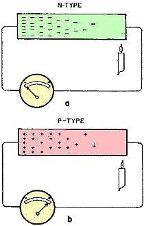
Fig. 1 - Seebeek effect. Movement of electrons in semiconductor
material caused by heating. a - N-type semiconductor. b - P-type semiconductor.
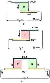
Fig. 2 - Peltier effect. An applied voltage forces electrons
to flow through semiconductor material, absorbing heat at one terminal and emitting
heat at the other.
Thermoelectricity is more than a century old. Thomas Johann Seebeck in 1821 was
experimenting in Berlin with a bar of antimony that had a coil of brass wire wound
around it and attached to its ends to form a loop. He noted that, when a junction
of the bar and wire was heated, a nearby magnetic needle was affected. Two years
before this event Oersted had discovered the magnetic effect of a current, and Seebeck
believed that he had discovered a magnetic effect caused by heat. The idea of a
current flowing in the conductors did not at first occur to him. Four years later
when Ohm discovered his famous law, he used the Seebeck effect to produce small
voltages.
Fourteen years afterward, Jean Charles Peltier, a French physicist, noticed that
when a current flowed in a circuit of two dissimilar metals, one junction between
the two was heated while the other was cooled. To us the Seebeck and Peltier effects
are complementary but, at the time of their discovery, they were imperfectly understood,
and it was not until 1857 that Lord Kelvin, then William Thomson, showed the exact
relationship between the two and postulated a third small thermoelectric effect,
now called the Thomson effect, caused by the thermal gradient in conductors.
The Seebeck and Peltier thermoelectric effects are small when ordinary metals
are used, and for over a hundred years the principal uses were for thermocouples
and thermopiles for temperature-measuring and heat-detecting devices. Thermoelectricity
could not compete with other electrical power-producing methods such as batteries
and generators as the power conversion efficiencies for thermoelectrics were generally
below 1%.
The recent advances in knowledge of solid-state physics, particularly in the
field of semiconductors, have brought about an upsurge of interest in thermoelectricity.
All conducting materials have measurable Seebeck and Peltier effects, but certain
semiconductor materials exhibit markedly greater effects than ordinary materials.
They also have the proper values of electrical resistance and thermal conductivity
necessary to give good performance in thermoelectric heat-transfer and power-generation
applications. Both n- and p-type semiconductor materials are useful. The first can
be thought of as having a surplus of free electron carriers, while the second type
has a deficiency. In p-type materials the current carriers are positive carriers
or "holes". In both types, the density of current carriers is very much, less than
in ordinary metal conductors.
Seebeck and Peltier Effects
To get a working concept of the Seebeck effect, visualize the current carriers
in metallic conductors as if they were a liquid, and in semiconductors as if they
were a gas. When one end of a piece of n-type semiconductor is heated, the conduction
electrons at this end, visualized as a gas, increase in pressure and are driven
to the cold end. In this way the cold end of n-type has a greater density of conduction
electrons and will show a negative potential with respect to the hot end (Fig. 1-a).
In a similar way, when one end of p-type semiconductor is heated, the "hole" conductors,
also visualized as a gas, increase in pressure and are forced to the cold end (Fig.
1-b). The latter then has a greater density of "hole" conductors and a positive
potential with respect to the hot end. Forming a thermocouple with n-type material
for one leg and p-type for the other is then an obvious way to combine them for
maximum thermoelectric voltage effect.
The Peltier effect can be understood in a similar way by visualizing the current
carriers operating in a gas-liquid transformation. Now consider a piece of n-type
semiconductor with a metal strip attached to each end. If we apply a dc voltage,
electrons are forced to flow from the negative pole of the battery around the circuit.
The electrons in the external metal conductor are visualized as a liquid and, when
they pass across the junction of the semiconductor, they leave the energy levels
of a liquid and enter the vapor state of a gas. This "evaporation" process absorbs
heat and a cold junction results (Fig. 2-a).
At the other terminal the electrons are forced by the potential from the gaseous
state in the semiconductor into the liquid state in the metal. This corresponds
to a "condensation" change of state, and heat is emitted and the junction becomes
hot. With p-type materials the carrier flow from metal to semiconductor is a cooling
transition, and the flow from semiconductor to metal is heating. With the same direction
of current flow, the heating-cooling effects at the junctions are opposite to those
of n-type material (Fig. 2-b). Combining an n-type leg and a p-type leg in a circuit
couple will create a hot junction and a cold junction for maximum effect (Fig. 2-c).
If heat can be continuously dissipated from the hot side of the couple, that is,
to a heat sink, a temperature difference can be maintained between the two junctions.
In other words, we have an electrical heat pump. The temperature difference between
the opposite ends depends upon the heat load to the cold side and the efficiency
of the heat sink. In practice, many couples are connected in series electrically,
with their heat pumping capacities in parallel.

Wall of thermoelectric elements makes a room air conditioner. RCA
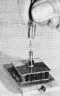
Experimental diode cooler for spot-cooling tests on electronic
components. Hughes
One of the popular misconceptions about Peltier coolers or heat pumps is that,
with the passage of a current through the semiconductor materials connected in couples,
heat is somehow annihilated at one junction. It is important to recognize that while
a quantity of heat may be "pumped" from an object while maintaining the object below
the effective environment-that is, heat is made to flow "uphill" - to do this electrical
power must be expended. The amount of power may range from a fraction to several
times the quantity of heat pumped. Thus, while Peltier devices lower the temperature
of the cooled object, they require the expenditure of energy. Therefore the heat
to be disposed of is larger than the heat removed from the object.
However, operating the Peltier unit in the heating cycle (that is, with current
reversed), the device is more efficient than resistive heating since, in addition
to the I'R heating, there is added the heat pumped from the cold side. Thus, as
a heat pump in the heating mode, it may supply up to several times more output heat
than an equivalent, purely resistive, heating element.
The total amount of heat pumped is directly proportional to the cross-section
area of the semiconductor material perpendicular to the direction of heat flow.
Since total cross-sectional area is the important factor, it makes no difference
whether the material is in many small pellets or a few large pellets. For each size
of pellet there is, however, an optimum cooling current. The only geometrical influence
on heat-pump performance is the ratio of length to area of cross-section. Thus for
a given L/A, the smaller the element the more heat can be pumped per unit area for
the same change in temperature and current.
Good Thermoelectric Semiconductors
A research group at Baso, Inc. in 1948 found that lead telluride, suitably doped
with an impurity, was an efficient thermoelectric material. In 1955, a detailed
study of bismuth telluride, a material first suggested by Goldsmid, led to the development
of associated alloys used for practical thermoelectric devices.
The ideal thermoelement would possess a high Seebeck coefficient together with
infinite electrical conductivity and zero thermal conductivity. The three properties
are combined in a single design parameter for the material, named the figure of
merit, Z, which is related to the Seebeck coefficient, S; to the electrical resistivity,
p, and to thermal conductivity, k, by the equation Z = S2/pk. These three
properties are not independent of each other, but depend upon the number of mobile
electron and hole carriers. The Seebeck voltage and the electrical resistivity are
inversely proportional to the number of mobile carriers, while the thermal conductivity
is approximately a linear function of the carrier density.
There is a never-ending search for better thermoelectric materials. To get optimum
efficiency or maximum power output, it is necessary to find the correct mobile carrier
density. Typical carrier densities for a good conductor such as copper, and a good
insulator, such as quartz, are 1023 and 109 carriers per cubic
centimeter, respectively. The range for semiconductors lies between 1014
and 1020 carriers. per cubic centimeter. A value of 1019 carriers
per cubic centimeter has been found best for lead telluride, bismuth telluride and
germanium telluride.
The figure of merit, the important material parameter mentioned above, is a function
of temperature. Generally, it reaches a maximum value at some particular temperature
and then drops off rapidly. At higher temperatures no potential difference is generated
by the semiconductor material. This fact has led to extended research in materials.
The maximum efficiency of a thermoelectric device is governed by the same Carnot
limitation as a reversible heat engine. That is, the greater the difference in temperature
between the hot and cold ends, the higher the conversion efficiency. Present-day
devices are inefficient energy converters averaging about 6%. A modern industrial
power plant with turbine generator can operate with a thermodynamic cycle efficiency
of 45% and an electrical generator efficiency of 95%. This results in an overall
thermal efficiency of 42%.
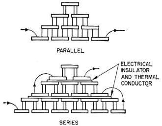
Fig. 3 - Two common configurations of three-stage coolers. In
such arrangements the cold junction of the first set of the thermocouples serves
as the heat sink for the second, etc.
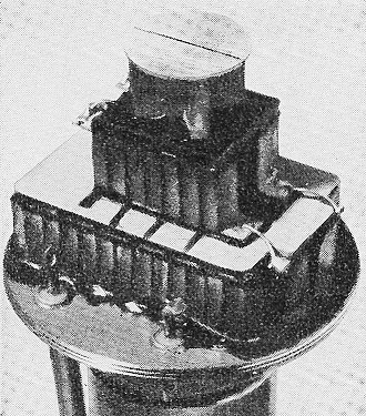
Infrared detector is cooled by three-stage cascaded thermoelectric
device. Operating on 2 amperes at 2 volts, the unit drops temperature from 25°C
to -77°C.
The forecast for thermoelectric generators in the next 25 years is that thermal
efficiencies may reach approximately 30%. While this is lower than that achieved
by the turbine-generator power plant, thermoelectricity may find its place in some
areas.
Practical Devices
In spite of lower efficiency, thermo-electric power generators have much to offer
for certain applications. The Atomic Energy Commission has sponsored a program to
develop several nuclear-fueled generators for SNAP (Systems for Nuclear Auxiliary
Power). One of the first products of this program, the SNAP-III radionuclide battery
was demonstrated in January 1959. The unit weighed about 5 pounds and had an output
of five watts to a matched load. The heat source consisted of a small amount of
radioactive Polonium 210, and a temperature differential of about 600°F is maintained
between hot and cold junctions. During the half-life of this material, the generator
is calculated to deliver a total of over 9,000 watt-hours of power, or the equivalent
of more than 100 pounds of the best chemical storage batteries.
A larger unit, SNAP I-A, weighing 175 pounds, has an output of 128 watts at 28
volts. This generator has 277 thermoelectronic couples imbedded in a shell enclosing
a nuclear fuel package of Cerium 144. The unit is smaller than a solar-cell system
and operates continuously. Provision is made to maintain the electrical output constant
as the nuclear fuel decays.
The Navy is interested in thermoelectric power generators for ship and submarine
use. Kerosene is the fuel source for a 5-kw generator being built that has many
combinations of voltage and current outputs ranging from 500 amperes at 10 volts
to 42 amperes at 120 volts. Lack of operational noise, compactness and the possibility
of using nuclear fuel make thermoelectric generators advantageous for submarines.
An interesting commercial development in small thermoelectric generators is a
portable unit to provide emergency power for operating a transistor radio receiver.
This unit consumers 1 pint of kerosene or fuel oil in 24 hours, develops 0.75 volt
and delivers 0.5 watt of power to a matched load. A built-in transistor converter
changes the 0.75-volt output to the 3 to 9 volts required to operate most transistor
radios.
In the field of heat pumping and refrigeration there are plans to employ thermoelectric
devices for small refrigerators for home, auto, boat, plane, and camping and water
coolers.
One manufacturer has designs for several sizes of refrigerators with from 1 to
4 cubic feet of capacity. The smallest size is designed for a 25-watt thermal load
and uses 30 bismuth telluride thermocouples 2/10 inch in diameter and 1/4 inch long.
The operating current is 20 amperes at 2.5 volts. The 4-cubic-foot model is designed
for a 65-watt thermal load, uses 80 of the same thermocouples. The boxes are insulated
with plastic foam 1 inch thick and will maintain an inside box temperature of 40°F
or lower when operating in an outside ambient of 90°F.
Another manufacturer is producing small thermoelectric refrigerators for installation
in all the new rooms of a Chicago hotel to provide guests with self-service ice
cubes.
In medical research there have been applications for controlled cooling of particular
areas of the body, for example, spot cooling of parts of the brain. These studies
are leading to increased knowledge of human physiology. Such a thermoelectric cooler
has been designed at Hughes Aircraft Co. and used at UCLA's Medical Research Center
for experimental brain research.
Thermoelectric cooling is being used to air-condition an experimental space suit
to keep an astronaut comfortable at a temperature of 80°F in environments up
to 135°F. A thermoelectric cooler-heater unit fits into the back of the suit
with the battery power source in the front.
Hughes Infrared detector is cooled by three-stage cascaded thermoelectric device.
Operating on 2 amperes at 2 volts, the unit drops temperature from 25°C to -77°C.
The electronics field offers countless uses for general and spot cooling of component
parts. Spot cooling is usually by direct conductive connection between the part
and the Peltier cooler. Power diodes, transistors, ferrite cores, infrared cells,
photocathode and photo-multiplier tubes, fluorescent light sources, etc. are all
temperature-sensitive components. Most solid-state devices are limited to a specific
maximum temperature of operation, above which their characteristics deteriorate
and reliability diminishes. So keeping temperatures down becomes important.
Infrared detector cells, important for guiding some types of missiles, have increased
sensitivity and lower noise out-put level when operated at temperatures below that
of dry ice. Obviously, it is not convenient to maintain a supply of dry ice or liquefied
refrigerant in each missile. Thermoelectric coolers have been successfully developed
for this important application. Such devices begin to operate the instant current
is turned on. A unit operating at 2 amperes and 2 volts achieves a temperature drop
from 25°C to -77°C, enough to cool an infrared detector down to its optimum
operating temperature. The Hughes cooler is a three-stage cascaded device using
cell loading of about 125 mw.
In the cascaded arrangement of thermocouple elements, the cold junction of the
first set serves as the heat sink for the second set, and the cold junction of the
latter cools the hot junction of the third set, and so on (Fig. 3). In this way
a greater temperature difference can be built up between the heat sink and the final
cold junction. Unfortunately, due to the temperature variation of certain material
parameters, not much is gained by employing more than three stages.
Such is the current state of thermoelectric technology. The great promise of
thermoelectricity is that, with some further advances which seem within our grasp,
it will perform a wide variety of tasks important to man's welfare more efficiently,
more simply and more conveniently than existing devices. As our knowledge of solid
state phenomena increases, its future appears to be well-nigh limitless.
* Senior staff engineer, Aerospace Group, Hughes Aircraft Co.
|


