|
February 1962 Radio-Electronics
 [Table of Contents] [Table of Contents]
Wax nostalgic about and learn from the history of early electronics.
See articles from Radio-Electronics,
published 1930-1988. All copyrights hereby acknowledged.
|
Along with the advent
of FM (frequency modulation) radio came an entirely new variety of antenna shapes
and configurations, compared to primarily a simple long, straight wire for AM (amplitude
modulation) radio antennas. Amateur radio operators (Hams) of course had been designing,
tuning, and using such antennas (as FM) for decades, but the average radio listener
was facing a whole new world of options for getting the most out of his receiver.
It is not that AM radio cannot benefit by similar antenna configurations, it is
just that the relatively long wavelength of AM station frequencies (540 to 1,700 kHz)
compared to FM station frequencies (88 to 108 MHz) represents a two-order-of-magnitude
increase in antenna element lengths, rendering them impractical for most installation
sites. For example, a quarter wavelength element for FM (not allowing for end effect
or other parasitic factors) at the bottom end of the band (88 MHz) is 33.5 inches,
whereas at the bottom of the AM band (540 kHz), the length is a whopping 5,464 inches
(163 times longer).
FM Antennas for Better Listening
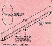
Fig. 1 - Simple FM made from a length of 300-ohm twin lead.
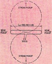
Fig. 2 - The basic folded dipole and its figure-8 pattern.

Various antenna configurations and radiation patterns.
Types of antennas and their characteristics
By Edward M. Noll
The antenna has always been important in FM. But with stereo multiplex FM, a
good antenna is absolutely vital, even in metropolitan areas. The signal-to-noise
ratio of the stereo signal is far below that of a conventional mono FM signal, and,
if the signal at the receiver input is inadequate, the multiplex subcarrier will
not be strong enough to lock in the receiver's multiplex circuits. Poor stereo separation
or complete absence of stereo may be the result.
A good antenna keeps local signals well above the level at which interference
and background noise can mess up the reproduced program. At the same time, longer
distance signals can be raised above the noise level, reducing fading and interference.
The stronger the signal delivered to the tuner input, the more it can be made to
exceed the background noise of the receiver.
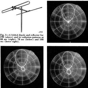
Fig. 3 - A folded dipole and reflector for FM (above) and its
radiation patterns at 88 mc (right), 78 mc (below) and 108 mc (lower right).
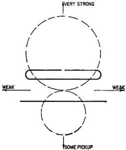
Fig. 4 - Folded dipole and reflector with its horizontal directivity
pattern.
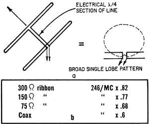
Fig. 5 - End-fire folded dipole and its single-lobe pattern.
The table shows length of the quarter-wave section.
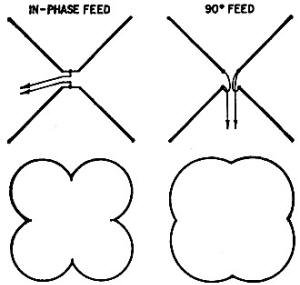
Fig. 7 - Turnstile feed arrangements and their effect on the
antenna pattern.
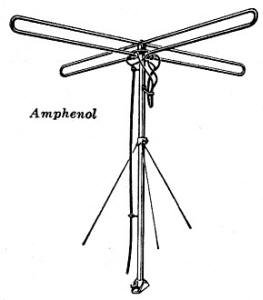
Fig. 8 - The folded-dipole turnstile is a popular FM antenna.
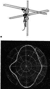
Fig. 9 - A typical turnstile (a) and its pattern at 98 mc. (b).
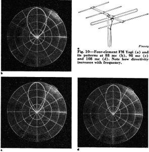
Fig. 10 - Four-element FM Yagi (a) and its patterns at 88 mc
(b), 98 mc (c) and 108 mc (d). Note how directivity increases with frequency.
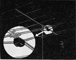
Fig. 11 - Broadband Yagi with antenna-mounted booster.
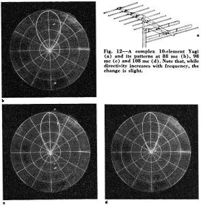
Fig. 12 - A complex 10-element Yagi (a) and its patterns at 88
mc (b), 98 mc (c) and 108 mc (d). Note that, while directivity increases with frequency,
the change is slight.
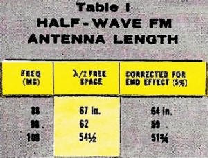
Table 1 - Half-wave FM antenna length.
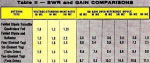
Table 2 - SWR and gain comparisons for antenna types.
Sensitivity of FM tuners is usually given in terms that relate microvolts of
signal to background quieting. This figure is generally presented as the minimum
signal strength required for a certain amount of db quieting (usually 20 or 30 db).
To say a receiver has a sensitivity of 1 μv for 3D-db quieting indicates that
an incoming 1-μv signal will reduce the normal no-signal background noise level
of the receiver by 30 db. If the incoming signal is strong enough to press down
the background noise by 40 db, the background, in a practical sense, can be called
noiseless.
A correctly installed antenna can do much to optimize the weaker and more distant
FM stations. By correct antenna positioning and orientation, these signals can be
raised above the background noise. They can be made strong enough to dominate interference
from local stations on nearby channels.
Built-in antennas are included with most FM receivers and tuners. The built-in
antenna is usually a piece of 300-ohm Twin-Lead stapled to the cabinet. Such a simple
antenna is often good enough for the stronger local stations. But reception is better
when the antenna is improved.
Attic- or window-mounted antennas help considerably if it is not possible to
go to a roof-mounted outdoor type. A ribbon-line folded dipole (Fig. 1) can be stapled
to attic rafters or other convenient mounting. The length of such a ribbon antenna
can be about 4 1/2 to 5 feet. Solder the ends together as shown. Break one lead
at its center and attach the 300-ohm transmission line that must be run between
the folded dipole and the antenna terminals of the FM unit. As shown, the antenna
is most sensitive when placed broadside to the received signal. When the transmitters
in the area are located in differing directions, mount it broadside to the weakest
signal you wish to receive.
An outdoor antenna is best if optimum performance is desired. There are a variety
of outdoor FM antenna styles, from the simple dipole to the high-gain Yagi. Let
us consider the physical and electrical characteristics of the more common styles.
Frequency, Bandwidth and Size
The FM band occupies a 20·mc span of frequencies between 88 and 108 mc. Spectrum-wise
it is positioned just above television channel 6. Hence the FM antenna is somewhat
shorter than low-band TV antennas, and the usual FM antenna is not nearly so elaborate.
Typical half-wavelength dimensions at the center and ends of the FM band are given
in Table 1.
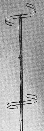
Fig. 6 - Stacked S-folded dipoles.
Most FM antennas are cut to the center of the band or on the low-frequency side
of center. This gives reasonable sensitivity over the entire span of frequencies.
Some drop in sensitivity is to be expected at band edges because of the 20-mc bandwidth.
If you want to receive a weak station near the band edge, you can increase signal
strength by choosing a length that resonates at or near its frequency (Table I).
Often a simple folded dipole (Fig. 2) is used as an FM antenna. It is a half-wavelength
long and has a resistance of 300 ohms when center-fed. Thus 300-ohm line can be
used to transfer the signal from the antenna to the 300-ohm input terminals of the
receiver. A horizontal dipole antenna has a figure-8 horizontal directivity pattern.
Thus its sensitivity is maximum broadside to the antenna element. (Minimum pickup
is in line with the antenna.) When installing an antenna in an urban or suburban
area, the two minima are spaced in the directions from which no FM signals are likely
to arrive. With station signals arriving from various angles, such an antenna does
not give optimum results. Nevertheless, in strong-signal areas it can usually be
positioned for good reception of all local stations.
If you are fortunate enough to live in a suburban or near-fringe area where all
FM transmitter signals arrive from approximately the same direction, a simple gain
type antenna (one with additional elements to increase the gain in one direction-see
Fig. 3) can be used. The reflector element, which is longer than the dipole, lowers
the sensitivity of the antenna on its side of the driven element and increases it
in a direction away from the reflector (Fig. 4). When using such an arrangement,
some 35% to 45% more signal voltage can be delivered to the receiver input than
with a single dipole.
The horizontal radiation pattern for the folded-dipole and reflector combination
at the center and two end frequencies of the FM band is given in Fig.3.
Table II shows the SWR and gain figures of the various styles of antennas at
specific frequencies in the FM band. Notice that the gain of the dipole and reflector
combination decreases with frequency. Remember that the reflector must be cut long
enough to act as a reflector at the low end of the band. The effectiveness of the
combination declines toward the high-frequency end.
A gain antenna must be oriented carefully for best reception from the weaker
FM stations you wish to receive. Such an antenna does have some back pickup and
can handle strong signals that arrive from the back. The single dipole is least
sensitive to signals in line with its individual antenna elements.
When a folded-dipole driven element is used, a 300-ohm transmission line is customary.
For a straight dipole, a lower-impedance line can be used. This can be 75- or 150-ohm
ribbon line or a 50- or 72-ohm coaxial line. Many FM receivers and tuners have terminals
for connecting either high- or low-impedance lines.
Occasionally two driven elements are used, as shown in Fig. 5. In this arrangement
two driven dipoles are employed. One dipole is driven in a manner that will place
it in quadrature (90° related) with respect to the second dipole. This can be
done by using a section of transmission line 90° (a quarter wavelength) long
between the points of attachment to the two dipoles. The physical length of this
90° section is determined by multiplying the quarter-wavelength free-space dimension
times the velocity factor of the particular transmission line. Typical lengths are
shown in the diagram.
The advantage of this so-called end-fire arrangement is that a cardioid (heart-shaped)
horizontal directivity pattern is obtained. It has a broad forward pattern that
makes the antenna sensitive to many angles of arrival as far as its forward directivity
is concerned. The side and rear pickup of the antenna is quite poor so noise and
interference pickup from the back are minimized. It performs well for a location
where signals arrive over a rather broad angle in the forward direction.
Turnstile Antennas
A popular FM antenna is shown in Fig. 6. The driven element is basically a folded
dipole. The folded dipole is shaped into a figure-S. This gives a much broader figure-8
horizontal directivity pattern. Such an antenna sacrifices its pickup, to some extent,
in a direction exactly broadside to the antenna element. Its pickup at angles quite
divergent from the broadside line is improved. Also, it does not have sharp minima
in line with the antenna element. Stacked S-folded dipoles permit higher gain.
An FM antenna can be made sensitive in more than two directions by using two
in-phase dipoles mounted at right angles (Fig. 7). The horizontal directivity of
this arrangement is like a clover leaf. However, there are now four minima and,
in orienting such an antenna, they can be troublesome if signals are arriving from
several directions.
The most common form of turnstile antenna is shown in Figs. 8 and 9. One of the
dipoles is fed in quadrature with the second. This 90° feed arrangement consists
of an electrical quarter-wave section of line between the two right-angle dipoles.
The 90° feed arrangement of the turnstile pair provides an omni-directional
horizontal pattern as shown. Such an antenna need not be oriented when it is installed
because its pickup is uniform at all compass angles. There are some minimum positions
which are not very deep, and therefore, not particularly objectionable. Conical
driven elements can be used to get a still more uniform omni-directional pattern.
Parasitic Antennas
Additional parasitic elements (Fig. 10) can be added to increase the gain of
an FM antenna and sharpen its directivity. This style of antenna is used to best
advantage in fringe and far-fringe areas. When long-distance FM stations arrive
from different directions, such an antenna is used with a rotator.
Yagi antennas have very high gain and a sharp horizontal directivity pattern.
The greater the number of parasitic directors, the higher the antenna gain and the
sharper the directivity pattern. If such an antenna is to be installed in a fixed
position, it must be oriented very carefully in the direction of the signal.
Such an antenna picks up local stations reasonably well, even though they may
not be in line with the most sensitive direction of the antenna. Hence in many locations
such an antenna can be oriented in the direction of the weak distant signal and
will still have enough pick up for the reception of local FM signals .:
Yagi antennas of this type must be broad-banded if they are to have reasonably
uniform sensitivity over the entire FM spectrum. When an FM enthusiast is interested
in receiving a weak long-distance station, it is possible to cut and assemble a
Yagi tuned to its precise frequency. An alternative to this plan is to make some
alterations in the element dimensions of a commercial Yagi to peak its sensitivity
at a given frequency. It is possible, at times, to obtain a channel-6 TV Yagi antenna
at a bargain price. The elements of this Yagi can then be cut down to a specific
FM frequency. Spacing between elements need not be changed.
The Yagi in Fig. 11 is a broad-band type. Note the booster mounted on the antenna.
Optimum dimensions for the dipoles permit the combination to display a more uniform
pickup over the entire 20 mc of the FM band. The reflector is cut into the low end
of the band; directors, the high end. The patterns of the model in Fig. 12 show
how the pattern sharpens when many elements are used. Hence the antennas must be
oriented critically to get the most out of them.
The radiation patterns in Figs, 3, 9, 10 and 12, and the information in Table
II are printed through courtesy of the Finney Co.
|


