|
July 1961 Radio-Electronics
 [Table of Contents] [Table of Contents]
Wax nostalgic about and learn from the history of early electronics.
See articles from Radio-Electronics,
published 1930-1988. All copyrights hereby acknowledged.
|
The early 1960s was an era
of significant change for the realm of in-home entertainment. Television was
transitioning to color, radio was transitioning from AM (amplitude modulation)
to FM (frequency modulation), and FM radio was transitioning from monaural to
stereo. Print media was beginning to include more color in its pages. The human
sense organs and brain were being called upon to process much more information
from sources other than real-world experience. For many people (me included,
having been born in 1958), seeing the world's natural and manmade features in
color was an amazing revelation, and our household was one of last in the
neighborhood to get a color TV. I never knew the Flintstone's pet dinosaur,
Dino, was
purple until sometime around 1969 I saw him on a friend's color TV. My
introduction to stereophonic music does not have as much of a stark place in
memory. Prior to high school (1972-1976), my radio listening was AM station
WNAV in Annapolis, Maryland. It was mostly local
talk (no Limbaugh types in the day), news, ballgames and a few hours of music
each day. Any WNAV'ers out there remember the "Second Cup of Coffee" show in the
mornings? My first stereo system was a
Reader's
Digest Model 800-XR AM/FM radio + 8-track tape player, bought in 1975, which I still have
and it's in near-new condition (I did upgrade the lame speakers within the
original housings). It was my first real experience of hearing separate left and
right channels. This 1961 Radio-Electronics magazine article discusses
the effort needed to get the FCC (Federal Communications Commission) to finally
permit FM stereo broadcasting - a typical bureaucratic boondoggle.
Clear Road for FM Stereo
How the Zenith G-E multiplex system works and why it was approved
over its competitors.
By Norman H. Crowhurst
We have been waiting for what to some people has seemed an inordinate length
of time, for a decision from the FCC that will enable stereo broadcasting to move
ahead. Now the green flag has come and a lot more people want to know what it means.
People are still asking how one stylus can get two-channel stereo out of a single
record groove; they are going to be equally puzzled about the transmission of two-channel
stereo over a single FM radio channel. The two techniques are parallel to a certain
extent. Both start with one microphone picking up the sound for the left channel;
another for the right. Then, for the benefit of people with "regular" monophonic
FM receivers, the right and left channels are blended into a single program and
transmitted. The program is sent out from the FM transmitter with a reduction of
about 1 db in amplitude from normal monophonic transmissions, to make room for the
stereo information which, we shall see, is also being transmitted.
To supply a stereo program to those listeners who have - or soon will have -
a stereophonic receiver or adapter, the output from the same two microphones is
picked up and combined in a different way. Instead of containing the monophonic
program - the sum of left and right - this combination contains the details in which
left differs from right. Instead of being called the sum, it can be - and is - called
the difference program. The sum can then be referred to as L plus R and the difference,
L minus R.
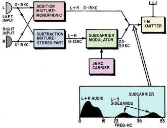
Fig. 1 - This block diagram shows how equipment might be hooked
up to produce a stereo FM signal. The pattern at bottom shows how the two program
components (L + R and L - R) modulate the FM transmitter.
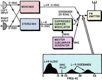
Fig. 2 - Removing the subcarrier improves transmission quality;
19·kc pilot helps receiving equipment reinsert the subcarrier.

Fig. 3 - Essential parts in a simple adapter for the new system.
(This diagram is the author's interpretation only and does not represent a design
or working schematic.)
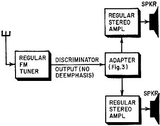
Fig. 4 - Stereo adapter connects between any (good) single-channel
FM tuner and the inputs to a stereo audio amplifier system.
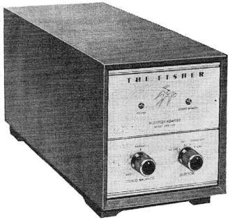
The new Fisher multiplex adapter.
Full fidelity for FM transmission consists of frequencies up to 15 kc. The stereo
mixture is handled with the same full fidelity as the mono channel. It is used to
modulate a subcarrier of 38 kc. Amplitude modulation of this subcarrier by frequencies
up to 15 kc produces "sidebands" between 23 kc and 53 kc (Fig. 1).
Amplitude modulation concentrates most of the energy in the carrier. To enable
this channel to be transmitted at higher level, improving its signal-to-noise ratio,
the carrier is removed, leaving only the sidebands. To demodulate this channel at
the receiver, the carrier has to be put back first.
To make this possible, a frequency exactly half the carrier frequency - 19 kc
- is transmitted. This comes between the highest main monophonic channel frequency
(15 kc) and the lowest sub-channel sideband frequency (23 kc), making it easy to
separate from everything else without any mistake (Fig. 2).
The receiver has two filters: a band filter to separate the sidebands of the
subcarrier from the main carrier modulation; a single-frequency filter to separate
the 19-kc pilot subcarrier. A frequency doubler reproduces the subcarrier, which
is added to the sidebands, so the stereo channel can be demodulated (Fig, 3).
Now we have two signals, the monophonic, or sum (L + R), and the difference (L
- R). As readers who have followed the discussions on multiplex will remember, it
is necessary to mix these, one in phase and one out of phase, to produce right and
left channels. To the newcomer, it must be explained that mixing the signals in
phase is equivalent to adding (L + R) to (L - R), which comes out 2L, (It works
out electrically as well as mathematically, as a little consideration of aiding
and opposing currents will show.) For the right channel, we subtract the two channels
(add them out of phase). (L+R) - (L-R) is equivalent to (L + R) + (-L + R), or 2R.
The matrix circuit that reproduces these left and right channels from mono (or
sum) and stereo (or difference) signals, and the usual de-emphasis to restore the
balance compensating for transmission pre-emphasis, complete the necessary conversion.
A simple adapter containing these parts, which G-E claims can easily be built into
a one-tube circuit, comes between the normal FM (single-channel) receiver and the
inputs to a normal stereo left-and-right two-channel system (Fig. 4). Other manufacturers
believe that a more complex adapter may be needed for satisfactory operation under
all conditions, and adapters with as many as six tubes are in the works.
Reasons for the Choice
In earlier articles we discussed the contenders who proposed various systems.*
The final contenders were slightly different from the ones we discussed then. The
systems between which the FCC decided were:
1. Crosby
2. Calbest
3. Multiplex Development
4. EMI (Percival)
5. G-E/Zenith
The Crosby and Calbest systems were the same as we previously described; the
Multiplex Development system we previously called the Burden system; the EMI (Electric &
Musical Industries) Percival system we briefly mentioned - it used a code signal
to "direct" the distribution of monophonic program between the stereo channels at
the receiver; the G-E/Zenith system is the final choice we have described.
Systems 2 to 4 were eliminated in earlier "heats" for various reasons. The Calbest
and Burden systems were rejected for essentially the reasons we criticized: they
involve a basic limitation in stereo separation at the transmitter; the Calbest
on the basis of frequency, the Burden over the entire range, by cross-mixing.
The EMI system was found quite successful in many respects. It did not degrade
either quality or dynamic range for either monophonic or stereo reception. If the
code signal were made part of original recordings - if discs were made by Percival
instead of 45/45-the system might well have been chosen as best. But the recording
industry is already committed to 45/45 and that's the kind of program that has to
be transmitted, most of the time. Existing stereo records need automatic means to
provide coded monophonic program. The FCC found EMI's system for doing this failed
to maintain stereo separation on some passages; notably, sustained tones became
essentially monophonic.
That left the systems numbered 1 and 5. The Crosby system uses a frequency-modulated
subcarrier with a proposed frequency of 50 kc and a deviation of 25 kc. The G-E/Zenith
system uses an amplitude-modulated subcarrier with a proposed frequency of 38 kc;
the carrier is suppressed and a 19-kc half-frequency pilot carrier is transmitted
instead.
At first hearing, this sounds complicated, But it permits maximum use of the
amplitude modulation for stereo without detracting from the main monophonic modulation
appreciably. Removing the subcarrier enables the sidebands to be transmitted at
much higher level, giving the stereo (difference) signal a better signal-to-noise
ratio.
Even at this, the G-E/Zenith system does not achieve the signal-to-noise ratio
on subcarrier that the Crosby system can. The table on page 27 gives the relative
degradation in signal-to-noise ratio for various signal components of the two systems
(theoretical) compared with full-deviation monophonic transmission.
There are three main reasons for the FCC decision in favor of the G-E/Zenith
system, the most important of which derives from the information shown in the table.
An important practical question is, "How will conversion of stations for stereo
affect their service area?" When they don't transmit stereo, it will not be affected
with either system, of course, but what happens during a stereo transmission?
The Crosby system considerably reduces service radius, whether the program is
heard in mono or stereo, but more on stereo than on mono. The G-E/Zenith system
only slightly reduces the service radius for monophonic reception of stereo, although
the reduction is somewhat greater for stereo reception than in the Crosby system.
The range for stereophonic reception would be only two-thirds as great as for monophonic
reception of the same program.
The fact that the Crosby system would deprive a larger area of any service during
a stereo transmission means either that the effective audience is reduced during
a stereo transmission, or power must be boosted.
This may be out of the question for many stations, already operating at maximum
power. But even if possible, it is undesirable, because of the greater possibility
of interference with either geographically separated channels on the same frequency
or adjacent frequency allocations in the same area.
The G-E/Zenith system can serve substantially all the area with at least a monophonic
signal during stereo transmissions, while a smaller area can receive the superior
stereo with the necessary adapters.
Theoretically, both systems are capable of full-frequency-range separation between
left and right, and of minimum distortion on both mono (sum) and stereo (difference)
channels. But adapters for the Crosby system have proved critical in achieving minimum
distortion.
Because it uses FM subcarrier modulation, with a wide deviation, the Crosby system
adapter has to eliminate any amplitude modulation at the subcarrier detector. This
is not easy to do. First a bandpass filter must pass frequencies from 25 to 75 kc,
while stopping frequencies below 25 kc. And then frequencies from 25 to 75 kc must
be limited and FM detected without any amplitude fluctuation.
The FCC felt the G-E/Zenith system offers the best prospect for producing receivers
that will consistently demodulate the subcarrier without introducing distortion.
Also, in their opinion, low-cost receivers of reasonable performance are a better
prospect with this system.
Subsidiary Services
The other reasons that favor the G-E/Zenith system over Crosby concern the use
of an additional subcarrier for other services (private) such as background music.
Although Crosby has maintained that his system does not exclude a background-music
channel, it does appear that the full advantage for stereo transmission and stereo
reception (which is where his system admittedly offers best potential) will disappear
if another subcarrier is squeezed in.
While a second subcarrier will degrade both systems, the G-E/Zenith system suffers
less than the Crosby system. Of 250 stations now authorized to use multiplex for
background music or other private purposes, 81 are in locations where there is no
other FM service. This would force an unfortunate choice if no second subcarrier
were permitted. The station must decide whether its listeners may have stereo, at
the cost of canceling an existing contract for private use. The G-E/Zenith system
makes it far more feasible for stations to do both if they have to.
Further, if the Crosby system were used, a relatively minor modification to any
stereo receiver would enable it to receive the private multiplex transmissions,
because they also use a frequency-modulated subcarrier (of different frequency).
The G-E/Zenith system, by using an amplitude-modulated subcarrier, avoids this possibility.
Additionally, the use of a different kind of modulation makes it much easier to
separate the stereo subcarrier from a private subcarrier.
One more question is going to be asked: How about people who already have Crosby
type adapters, a few of which have been made by some manufacturers? This question
concerned the FCC somewhat in making their decision. Their conclusion was a sensible
one. Tests on a number of these adapters found that none of them consistently met
high-fidelity standards. It would be just as foolish to decide on a system merely
because a relatively small number of people have equipment for it (especially if
that decision would prejudice the quality of reception for everyone else) as it
would be to choose a system for its so-called compatibility with AM-FM experimental
transmissions.
Such AM-FM transmissions will continue for a while, until the majority of people
have the new adapters. But the AM-FM variety of stereo can never hope to produce
good quality as the new multiplex. So it would be foolish to limit the whole future
of stereo, merely because some people already have some enjoyment from this system,
while waiting for something better. Now we've got the something better - let's have
it. That's the substance of the FCC decision. We agree.
* Radio-Electronics, March and July, 1959.

How Signal-to-Noise Ratio of Stereo Systems Compares with Standard
FM Transmission and Reception
|


