|
February 1964 Radio-Electronics
 [Table of Contents] [Table of Contents]
Wax nostalgic about and learn from the history of early electronics.
See articles from Radio-Electronics,
published 1930-1988. All copyrights hereby acknowledged.
|
In "The G-Line Transmission Line"
from a 1964 issue of Radio-Electronics magazine, Owen Patrick recounts
his innovative solution to bring distant TV signals to his Carmel Valley home,
spurred by his wife's desire for "good channels" enjoyed by neighbors atop a
ridge 5 miles away, despite a 100-mile gap from broadcast sources like San
Francisco. Facing high-loss coaxial cables and problematic open-wire lines,
Patrick opted for a surface waveguide dubbed the G-line - a single insulated
wire developed by George Goubau (the "G" in G-line) in 1953 - offering low loss
(6 dB/mile), no radiation, and a 300-ohm impedance, ideal for spanning 3,400
feet from Saddle Mountain's 600-foot peak. Using No. 6 aluminum wire with
polyethylene insulation and custom launchers made from aluminum tubes and
Plexiglass, he matched the G-line to 72-ohm coax, overcoming terrain challenges
with minimal cost and maintenance, delivering Perry Mason to his valley-bound TV
after six years of reliable service - proving both his ingenuity and the
G-line's prowess for electronics hobbyists yearning for distant signals.
The G-Line Transmission Line
Like a glass of water without the glass. This single, unshielded
transmission line is nonradiating, and has extremely low loss.
By Owen G. Patrick
My wife (bless her un-electronics-oriented little heart) had been chipping away
for quite some time with "Why can't we have all those good TV channels the Cinch
Joneses get?"
My explanation that we live in a valley, walled in by mountains, while the Joneses,
though a mere 5 miles away, are in the open; that the "good channels" are 100 airline
miles from the both of us, but they could receive them and we could not, cut little
or no ice at all.
"Well, you're in electronics, so do something about it" was her understanding
reply.
When neighbor Bill added his "Say, why don't you -" to hers, the ground was freshly
plowed and ready to seed. Perhaps I could make like a modern-day Merlin and conjure
up those "good channels," thus making Number One happy. I must admit that, in addition
to the stimulus of the challenge, I too liked Perry Mason.
There were acceptable signals from San Francisco, San Jose, Sacramento and Oakland
atop a 600-foot hill known locally as Saddle Mountain. The big problem was how to
transport all that flickering drama over some 3,400 feet of rough terrain to our
house on the floor of Carmel Valley.
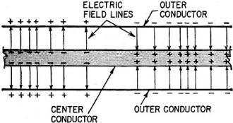
Fig. 1 - Pattern of charges and imaginary, symbolic electric
field lines describe electrical configuration on ordinary coax cable.
I began to consider common forms of transmission lines, and found that none were
right for us. Coaxial lines, even the more recent types developed for community
antenna distribution systems have fairly high losses in the upper vhf. These lines
are also expensive and require messenger support, which means frequent poles and
special equipment.
The relatively high loss of 3,400 feet of this line would also require an antenna-site
amplifier, which means duplexing power and rf on the transmission lines. Open wires
are not as lossy as coaxial lines, but they too present problems, not the least
of which is radiation.
If lines with spacers are used, there will be losses in the dust and moisture
bridges formed at each spacer. Open-wire lines (without spacers) were considered
- two wires under tension, separated only at the supporting poles - but this type
of line will modulate the signal, causing video flutter somewhat like sound bars.
This is due to a rapid impedance variation when the lines "sing" in gentle winds.
Also, this type of line is subject to bird-perching, which usually results in the
conductors being shorted together.
I finally decided to abandon the usual lines and techniques and to investigate
waveguides. Not the rectangular or round "plumbing" usually associated with the
term, but the external waveguide, a "surface waveguide," as it was termed by George
Goubau, who developed it at Fort Monmouth in 1953.
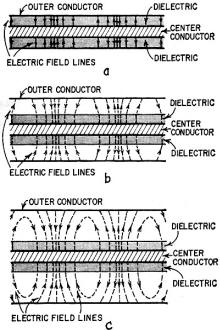
Fig. 2 - This is how G-line develops logically from coax.
In (a), dielectric is continuous from inner to outer conductor; field lines are
straight. In (b), discontinuity appears in dielectric at boundary between plastic
and air (their dielectric constants are different) and lines curve. Drawing (c)
shows how field lines begin to curve back onto center conductor as outer conductor
is moved farther away.
The G-line, as it came to be called, is just a single insulated wire. When rf
power is properly given to and taken away from this single conductor, it responds
with some amazing results. Its loss is very low, approximately 6 db/mile over the
vhf TV band. This means the output voltage from a 1-mile line is half that of the
input. Unlike coax or open-wire line, its loss does not increase with frequency.
It does not radiate. Its impedance is approximately 300 ohms, and it is inexpensive.
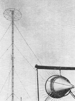
The launcher in the foreground feeds 1,250 watts of vhf power
via G-line to a small directional array halfway up the medium-wave tower in the
background. This installation is in Munich, Germany.
G-line is not a panacea for all situations. For those of you who live in an area
given to long periods of snowfall, read no further, for this and heavy ice loading
on the line will increase attenuation severely. Rainfall and fog, however, affect
the line very little.
If a situation requires abrupt sharp turns, the line can make it, but the rf
cannot, and will spit right off the turns. This doesn't mean you can't make turns
with the G-line. It just means that you have to make the turns gently, with a large
radius.
The G-line's last shortcoming is that it must be held clear of all objects for
a radius of a half wavelength at its lowest operating frequency. This includes buildings,
poles, the ground, metals and foliage.
Why - and How - It Works
Sommerfeld, in 1899, suggested the possibility of an external waveguide, but
attempts to transmit rf energy in this way failed. Then George Goubau, a German-born
physicist, discovered that all the line needed to make it propagate was insulation.
Examining the electric field within a longitudinal section of solid-dielectric
coax line, you can better understand the role of the insulation Goubau found so
necessary. The electric field lines vary in direction and magnitude with the distance
along the line. The entire pattern, maintaining relationships shown in Fig. 1, moves
away from the source at nearly the speed of light. Notice particularly that the
electric lines are shown beginning on charges on the surface of a conductor and
extending to charges on the opposite conductor.
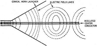
Fig. 3 - Gradually expanding outer conductor is means of
transforming coax into G-line. One such "launcher" must be at each junction between
G-line and coax.
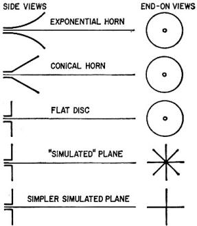
Fig. 4 - Exponential or conical horns are near-ideal transformers;
actual or simulated disc termination is simpler to make and nearly as effective.
All of this is just another way of saying that there is a difference in potential
and that electric lines of force are depicted as beginning and terminating on charged
bodies. That is, they begin and terminate on charged bodies if the transmission
line is not to radiate. Herein lies the problem, for what we plan to do is to expand
the outer conductor gradually, until it becomes so large that, in effect, it doesn't
exist electrically.
Normally this would mean that the electric lines of force beyond this point would
have only one body on which to begin or end, and hence could detach themselves from
the conductor and join heads to tails, forming closed loops that move away from
the wire, taking all the energy with them. That is, if the outer conductor is removed,
we expect the inner conductor to become an antenna. This is true if the dielectric
before and after expanding the outer conductor is the same (air, as an example).
However, our example is a solid-dielectric line, and the secret to the operation
of the surface waveguide lies in continuing this solid dielectric after the outer
conductor is removed.
Where the outer conductor has an increased diameter, the dielectric is no longer
all solid; it is part air and part solid. The speed with which the charges move
on the surface of conductors de-pends, among other things, on the surrounding dielectric.
The charges, to which the electric lines are attached, tend to move with a greater
velocity on the surface of the outer conductor than on the inner conductor, thus
forcing the electric lines to curve (Fig. 2).
If we continue this process, gradually making the outer conductor larger and
larger, the electric lines will bend in an arc so that they begin at a charge of
one polarity on the inner conductor and end with an opposite charge on the same
inner conductor (Fig. 3). Thus the electric field becomes imprisoned by one conductor
and cannot detach itself, whereupon the expanded outer conductor is unnecessary
and can be omitted.
In practice, the enlarged portion of the outer conductor is called a launcher.
A complete transmission system requires one at each end of the line. The one at
the receiving end has been called a catcher.
All this seems to suggest that these launchers should be exponentially shaped.
Experiments show that this form is not necessarily best, and in any case, not many
of us have the wherewithal to construct such a gadget. I decided to corrupt the
optimum in favor of a design that was easy to make and much less expensive. Fig.
4 shows the natural transition from the ideal to the simplified practical. This
simplification only adds about 1 db loss overall.
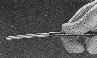
Fig. 5 - Author used No.6 aluminum wire with plastic insulation
for G-line.
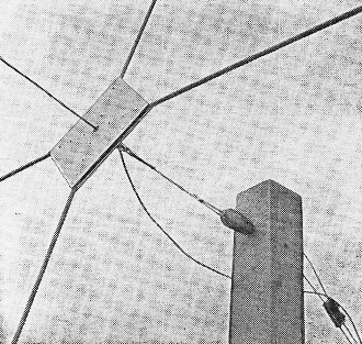
Fig. 6 - Front of launcher, looking from G-line side, showing
support pole and guying arrangement.
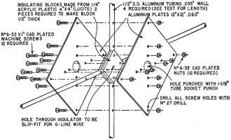
Fig. 7 - Exploded view of launcher assembly.
Put One Up
The wire I used in our system is No. 6 aluminum with a black commercial-grade
polyethylene jacket (Fig. 5). Aluminum was selected because this system consisted
of two 1,700-foot spans and here the weight is important. Any plastic-insulated
wire will do, such as common No. 14 or No. 12 solid-copper house wire. Rubber-insulated
and so-called "weatherproof" wire should not be used; those dielectrics are lossy
and absorb power.
Ideally, the line should be constructed from wire with an overall diameter twice
that of the conductor itself. However, variation from this formula does not change
the performance greatly.
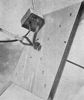
Fig. 8 - Rear of launcher shows "eye" bent into aluminum
wire, and nylon support rope. Box on back of launcher "sandwich" is transformer
to match G-line to 72-ohm coax. Short piece of ribbon lead-in goes from 300-ohm
side of transformer to end of G-line.
Our launchers were made with four 1/2-inch x 6-foot aluminum tubes located between
and along the diagonals of two 12-inch x 0.060 inch aluminum squares (Figs. 6, 7).
Two small squares of 1/4-inch Plexiglass or Lucite with holes in their centers to
admit the bared end of the wire form the insulator block. A knockout punch cut relief
holes in the centers of the two aluminum plates. The entire sandwich was secured
by 1-inch 6-32 machine screws.
The size, height, weight and whether or not "deadmen" will be used at the terminals
of the G-line will depend on the particular circumstances. Saddle Mountain's two
1,700-foot catenaries were suspended between 6 x 6-inch x 10-foot posts set in the
ground 3 feet and tied back to expandable anchors. These supports were later found
to be far more rugged than necessary since this line required only a 200-lb stress.
Be careful not to exceed the maximum load rating of the wire under the strongest
winds expected in your area.
The tie between the supports and the line is 1/4-inch nylon rope. Since nylon
is very slippery and doesn't knot well, it was bound with copper wire. Nylon rope
can be kept from unraveling by fusing the ends with a match or cigarette lighter
flame.
The bared end of the G-line is passed through the hole in the launcher insulator
(Fig. 8). A slotted bolt connector is slipped over the wire at the rear of the launcher
and the wire is then formed around a small cable "thimble" and once again passed
through the wire connector.
Once the connector is in place, the nylon tether is secured to the thimble and
the G-line is ready to raise.
In our system, 72-ohm coaxial feed lines are used to and from the launchers.
Weather-tight transformers such as Jerold's model TO-374 or Taco's Magi-Mix No.
1597 match the G-line's 300-ohm impedance to that of the coaxial line.
Even though transformation to an intermediate impedance of 72 ohms between the
G-line and the TV set required a transformer at both ends, it was well worth the
small additional cost to be able to run the interconnecting line next to water pipes,
on the ground and through walls with complete freedom. With 300-ohm line, a transformer
should still be used, even though the impedance of the G-line matches that of the
ribbon. A 300-ohm line is balanced, and the G-line is inherently unbalanced.
Our system has been in operation more than 6 years. It has survived winds over
80 mph and has withstood the tests of time and weather with complete success. Its
entire cost was less than that of the set we couldn't use without it and everybody's
happy. Now don't let a little thing like a mountain range stand between you and
Perry Mason!
***
Since the name G-Line is a trade mark used by Surface Conduction, Inc., for their
products which are also protected by patents, we have asked for and received permission
to publish this article under this name. The permission was given in view of the
fact that it represented a private study proving both the ingenuity of the author
and the reality of the G-Line.
|


