|
|||||||||||||
 |
|||||||||||||
Playback Preamp for Stereo Tapes |
|||||||||||||
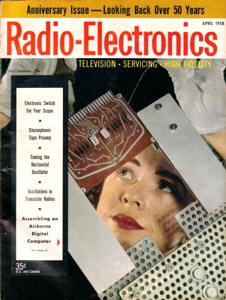
Hmmmm.... at the time I marked this stereo tape playback preamp project for posting I must have had a really good reason for it, but now I can't recall what that really good reason was. Maybe it was simply to mark the point in time when stereophonic electronic equipment was just beginning to be mainstream. Oh well, somebody somewhere will do a Google search on the topic someday and will be elated to find this. Besides, even though the use of vacuum tubes and magnetic tape is way outdated, there is a discussion of hi-fi audio that is still relevant. The article appeared in a 1958 issue of Radio-Electronics magazine. Thanks for your indulgence. Playback Preamp for Stereo Tapes By A. C. Moller. Jr.
Inexpensive unit lowers cost of stereo tape playback systems. Careful construction makes for professional appearance. Plenty of room inside case. Twisted wires are heater leads.
Circuit Schematic of the 2-Channel Preamp. R1, 2 - 100 ohms, 1 watt Now that stereophonic tapes and equipment have become plentiful and so many fans are purchasing tape decks, it seems apparent that a good two-channel tape preamp is the answer to inexpensive stereophonic sound. This two-channel preamp is relatively easy to build, even for the amateur audiophile. Its total cost is less than $30. In complicated hi-fi systems the two-channel preamp eliminates the constant changing of input and output leads. I leave the unit connected permanently to the stacked stereophonic heads on my tape unit. All recording is done with a separate head, thus enabling me to monitor freshly recorded sound with one channel of the preamp or use the two-channel preamp for all playback of tapes. The unit pictured has been designed to the proper response curve for NARTB recorded tapes. This is accomplished by the feedback loop consisting of a 680-ohm resistor (R12) and the 51,000-ohm resistor (R9) feeding through the .001-μf capacitor (C4). The resulting curve provides approximately 15-db boost at 20 cycles and 15-db cut at 15,000 to 20,000 cycles, which will equalize to a substantially flat response output when using NARTB recorded tapes. The unit has been tested with a scope and provided an almost perfect waveform from 20 cycles to beyond 30,000. There is a slight amount of deformity at approximately 500 cycles, but not enough to distort the signal excessively. The preamp is built into an aluminum chassis box 5 x 7 x 3 inches which encloses all components, thus minimizing hum as well as providing a neat appearance. Two 12AX7's are used, one for each channel, working from a single power supply. It uses a full-wave transformer with a 6.3-volt heater supply. Two selenium rectifiers are employed. Three 40-μf capacitors do an excellent job of filtering the B-plus. It is important to keep the power supply as far from the input jacks as possible and take other precautions to keep the hum level at a minimum. Placement and orientation of the power transformer are equally important. Heater leads are tightly twisted and dressed as close to the chassis as possible. A 100-ohm hum balance potentiometer reduces any remaining hum to a minimum. A 1-megohm potentiometer in the output of each channel controls volume and balance. The controls also provide some tone-control compensation by reducing bass boost as the control is retarded. If the unit is used with leads in excess of 6 or 8 feet, a 6C4 cathode-follower output stage can be added if desired. It is not necessary except in extreme cases. All ground connections are made to a No. 14 copper bus and grounded at the input jacks. All parts for the preamp are easily obtained at most radio parts supply houses. Construction time, including drilling the chassis, is approximately 6 hours. If hum is present, check all connections and parts placement. Also check each channel separately as a bad 12AX7 is sometimes encountered.
Posted July 11, 2022 |
|||||||||||||
 |
|||||||||||||
|
|||||||||||||



|
||||||||||||||||||||||||||||||||||||