|
November 1967 Radio-Electronics
 [Table of Contents] [Table of Contents]
Wax nostalgic about and learn from the history of early electronics.
See articles from Radio-Electronics,
published 1930-1988. All copyrights hereby acknowledged.
|
Even as recently as 1967,
when this "Rotary Stepping Switches - They're Everywhere" article appeared in
Radio-Electronics magazine, the vast majority of telephone switching
stations used electromechanical (EM) stepping switches. No computers were involved.
If you have ever been inside one of those facilities, the cacophony of clacking
switches will be forever imprinted on your memory. Nowadays all the switching is
performed by computer-controlled solid state devices. The only sound you hear is
cooling equipment fans. The EM stepper switch stations also had cooling systems
with fans, but the contact clacking was so loud that it drowned out the fans. Part 1,
here introduces the basic configurations and functions of rotary stepping switches.
The December issue has Part 2, which covers applications like counting,
selecting,
routing, and sequencing.
Rotary Stepping Switches - They're Everywhere
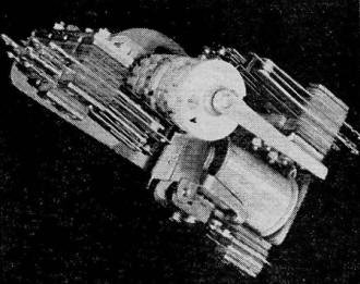
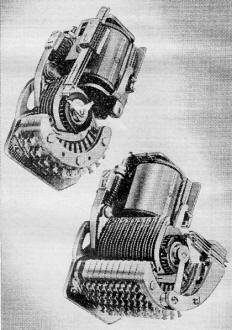
A cam-operated relay with 36 separate steps per cam and 3 banks
of switches.
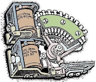
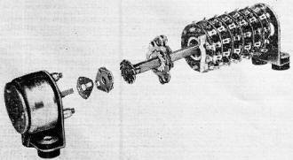
The minor switch has a motor and a release magnet, and a maximum
of 10 steps.
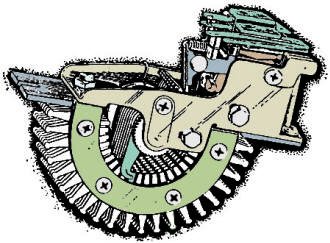
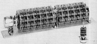
This 22-point rotary switch has 6 contact levels and a set of
interrupter springs.
Part 1 - How they work and what you should know about them
By Tom Jaski
Every time you dial a telephone, you activate nearly a dozen electromechanical
devices whose functions you probably have never figured out clearly. The voltage
pulses produced by an interrupter switch, in the telephone base, travel through
the phone line to the nearest central office. At this office, the call is routed
by the actions of a series of rotary stepping switches.* These switches perform
jobs that would take many relays, and they do these jobs faster and occupy less
space than relays do.
Wired a certain way, steppers can perform the same operations over and over again.
They provide complete isolation between controlling and controlled circuits. These
desirable characteristics are two of the reasons telephone systems still use steppers.
Other uses: remote control of radio and TV transmitters; counting items on a factory
production line; selecting circuits for monitoring gas pressure, liquid volume,
heat and cold, and similar measurements in factories and warehouses.
Abundantly available in surplus for some years now, rotary stepping switches
were used as line finders in early automatic telephone exchanges. In association
with Strowger switches† (two-motion, 100-point switches) they have, since
1918, carried literally billions of signals.
Cams
Apart from the Strowger switch, there are four basic types of rotary stepping
switches (or rotary stepping relays, as they are sometimes called). First, there
is the pawl-driven relay, with cams which open and close contacts. The top photo
shows one example. Each set of contacts is completely separate from the others.
Regular relay-type contacts and springs are used in any assortment that is normally
used on relays. Cams are available with up to 36 intervals. For each revolution
of the shaft, the contacts can be opened or closed as much as 36 times.
In addition to working contacts, some rotaries use off-normal and self-interrupter
contacts. Off-normal contacts are actually a form of reset. They are operated by
a separate cam, only once per revolution, and only when the switch has been stepped
away from a rest or "home" position.
Self-interrupter contacts are made for the heavy duty of interrupting the motor-magnet
current without excessive arcing. They are operated by the armature directly, in
the off position. Thus, if the current is supplied. to the magnet through the interrupter,
the coil will energize, open the contact, de-energize, close the contact, and so
on. The rate of self-interrupted operation is limited by the mechanical inertia
of the moving parts, and is often further decreased by external circuitry.
The working contacts on this stepper are limited to three stacks, and the relay
is not particularly suited to such operations as selection. It is designed for sequential
operation where only a. few contacts are needed.
The driving mechanism for this relay, as for other stepping switches, can be
either direct (the motor magnet operates the pawl directly) or indirect (the magnet
charges a spring which operates the pawl when the coil de-energizes). The indirect
drive is more reliable, for each stroke is exactly the same as the one before -
even if the coil current varies, and provided the relay operates at all.
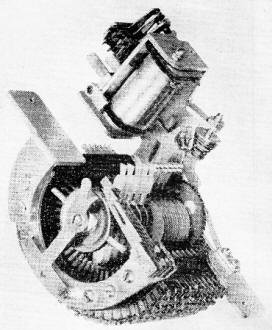
The Automatic Electric type 45 switch.
Compact steppers with 11 contacts each.
Single Wipers
The second type of stepping switch (center illustration) has been used for some
time in telephone work. It's called a minor switch, because it is often used with
a Strowger, or major, switch. The one shown is directly driven. Its shaft is driven
by a pawl and ratchet, which are driven in turn by the motor-magnet armature. The
shaft carries fingers which wipe across 10 contacts in each layer or bank. A minor
switch may carry as many as 6 banks of contacts.
In this type of switch, the dog that holds the ratchet is not fixed, but is attached
to another arm. This arm can be operated by a second magnet, the release magnet.
When energized, the release magnet causes the dog to be lifted from the ratchet,
and a return spring pulls the contact wipers back to "home" position. Note the off-normal
contacts operated by the roller cam on the shaft. A self-interrupter, if used, would
be operated by the motor-magnet armature directly.
Double Wipers
The third and older type of rotary switch (bottom picture page 39) has a double
set of wipers. By continuous rotation, one wiper from a set always touches at least
one contact. There's no return mechanism; to get to the starting position, the switch
must be stepped forward to "home." As in previous examples, off-normal contacts
and a self-interrupter can be used here. The switch can accommodate up to 6 banks
of 22 contacts. Wipers can be so connected and adjusted that 2 banks can be scanned
sequentially. Thus the switch can have 44 contacts in 3 levels.
A modern version of this kind of rotary switch is the Automatic Electric type
45 (see photo). This is an indirectly driven switch with 25 contacts per bank; a
maximum of 10 banks per switch can be used. The contact banks are removable so that
as few as are needed can be used. In addition, the wipers can be arranged so that
instead of 10 levels of 25 contacts there are 5 levels of 50 contacts.
Photo at right shows two compact rotary stepping switches, the Automatic Electric
types 40 and 80. These are also indirectly driven. The contacts are mounted in a
120° arc, and each set of wipers has three parts. Continuous scanning of 10,
20, or 30 contacts is thus possible. The type 40 has a maximum of 6 levels, and
the type 80 has
10. These switches are very compact, the 40 requiring hardly more space than
an ordinary telephone relay. Various types of contacts are available-shorting, non-shorting,
gold-plated, etc. So are different coil voltages. Note again the off" normal contacts
and ·also the arm on the coil armature. This arm can be used to operate interrupter
contacts.
Switch Diagrams and Circuits
Conventional switch wafers are used in this rotary stepper.
Ledex rotary switch uses relay contacts for heavy duty.
A different type of construction is used in the Ledex rotary solenoid (see photo):
the contacts are mounted on conventional rotary-switch wafers. The switch operates
as follows: The armature has a collar with three sloped ball races; the housing
has three corresponding ball races. The armature collar rides on these balls, and
a spring rotates the armature so each ball rests in the shallowest part of its race;
this is with the coil not energized and with the armature as far out of the coil
as possible. When the coil is energized, the armature is pulled into the coil. This
causes the armature to rotate against the spring. Rotation is 30° for each step.
An index mechanism prevents the shaft from returning with the armature. On the original
Ledex switches, standard switch wafers were used, and these are the kind found in
surplus stores. Later models (see photo below) use relay contacts for greater reliability
and heavy-duty switching.
When considering control diagrams for rotary switches, it does not matter which
type of switch is used (excepting the minor switch) so long as there are sufficient
contacts. Otherwise, switches differ mainly in the amount of current required for
operation and in the current their contacts will carry.
Fig. 1 contains both telephone and industrial symbols for the steppers, relays
and associated components in the control diagrams that follow. Industrial symbols
are used for simplicity, but telephone-type symbols are also shown to permit comparing
these diagrams with those of manufacturers. For those of you unfamiliar with industrial
diagrams, many of these symbols will take a little getting used to. The same is
true of the industrial-diagram practice of separating the essential elements of
devices, such as coils and relay contacts. However, this technique results in simplified
schematics which show the sequence of events. Fig. 2 is a simple example. Like most
circuit diagrams, you read it from left to right.
Industrial and Telephone Symbols
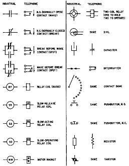
Fig. 1 - Industrial schematic symbols are different from those
used in electronics.
Pulses arrive at the left of the diagram. Since the pulse line is usually long,
it must not carry the heavy current necessary for operating the motor magnet of
the stepping switch. The pulses trigger low-current relay coil 1CR. The coil, which
is energized by each pulse, closes contacts 1CR-1 which are in series with the motor-magnet
coil. The motor magnet then causes the armature to advance a step each pulse.
Contact Arc Suppression
Since the motor magnet may cause arcing across contacts 1CR-1, an arc-suppressing
network consisting of a resistor and capacitor in series are shunted across this
coil. Values are determined by coil current and voltage, and range from 0.005 to
0.5 μF for capacitors and from 10K to 0.5 meg for resistors. Exact values are
usually found through trial and error.
In Fig. 3 the arc-suppressing network is replaced by a varistor, a semi-conductor
element which increases its resistance as the applied voltage increases. The result,
in either case, is a slow damping of the magnetic energy in the coil. This energy,
produced by the collapsing magnetic field, creates the contact arcing.
The circuit of Fig. 3 is that of a semiautomatic selector. Incoming pulses energize
relay 1CR. This relay does two things: through contact 1CR-1 it energizes the motor
magnet of the stepping switch, and through contact 1CR-2 it triggers slow-release
relay 2CR.§ A normally closed contact (2CR-1) prevents the connection of the
wiper to the battery at each step. When the proper controlled circuit has been selected,
the pulses cease. After a short delay, relay 2CR closes its contacts.
Two things now happen: The selected contact is connected to a battery (the B
+ line), starting a controlling pulse, and slow-operate relay 3CR is energized.
After another delay this relay stops the controlling pulse by opening normally closed
contact 3CR-1 in the wiper circuit. Second, 3CR closes contact 3CR-2 which energizes
the release magnet on the stepping switch.
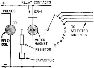
Fig. 2 - Simple remote-control circuit.
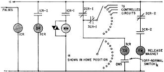
Fig. 3 - Typical minor switch control. circuit has semiautomatic
selector feature.
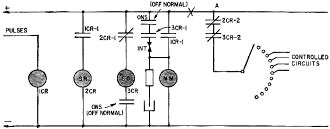
Fig. 4 - This circuit makes switch step forward to "home" at
end of its sequence.
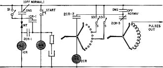
Fig. 5 - When S3 closes, 3 pulses are transmitted and switch
then steps "home."
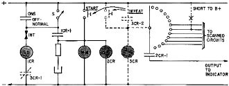
Fig. 6 - When activated, this circuit will scan all the switch
contacts, then stop.
Note the use of off-normal contacts (ONS). Relay 3CR cannot energize until the
switch is away from "home." Notice too that neither relay 3CR nor the release magnet
can energize until 2CR has released. Since 3CR is slow operating (meaning also slow
release), and the wiper is connected through normally closed contact 3CR-1, the
switch wiper remains disconnected until after the switch has returned home. What
has happened? Incoming pulses have selected a circuit, a control pulse has been
delivered, and the switch has been returned home. Duration of the control pulse
depends on 3CR. The pulse lasts as long as it takes this relay to open contact 3CR-1
in the wiper circuit.
Fig. 4, a similar circuit, outlines the circuit for a rotary switch without a
release magnet. In this case 3CR also closes a circuit to the interrupter, allowing
the switch to step forward to "home" by itself, which will happen in about 1/3 second.
3CR must remain closed that long. The off-normal contacts will stop the switch.
In using rotary switches in the self-stepping mode, it's best never to rely on a
relay to stop a switch. The interrupter contacts are much faster than any relay,
unless they are slowed down by a relay.
Such is the case in the circuit of Fig. 5 (although even so, the off-normal springs
are relied upon to stop the switch). This is a pulse-sending circuit. Switches S3
and S5 are two of a set of nine. (The others aren't shown for simplicity's sake.
Note also that usually no more than one or two switchbanks are shown, even though
the switch may have several more.)
With S1 open, and S5 closed, the following actions occur: Push the START button.
The rotary switch takes one step and gets off normal. This condition closes a path
to interrupter I, which energizes slow-operating relay 1CR. After a pause, 1CR energizes
the motor magnet for yet another step, and so on. Each time the rotary switch steps,
a pulse is sent out over the second bank of contacts. When the switch gets to step
5, five pulses have been sent out. Now relay 2CR is energized through the first
switch level. This cuts off the pulse line for outgoing pulses. It also connects
the motor magnet directly to the interrupter, and the switch steps rapidly forward
to home. Since 2CR is a slow-release relay, all these actions can happen while 2CR
is closed. In home position the off-normal springs cut off the magnet and the switch
stops.
If switch S1 is closed and S2 through S10 are left open, the sender will continue
to send out pulses so long as S1 is left closed. The pulse rate depends on 1CR,
and can be chosen as slow as 2 operations per second. Normally it will allow 10
pulses per second.
Automatic Scanning
The same principle of slow stepping is used in the circuit of Fig. 6, a device
that will scan all switch contacts, for example, to detect a voltage or a ground.
A relay can be included in the output circuit to stop this switch when such an event
occurs. This option is shown in dotted lines. Otherwise the circuit will scan once
and stop, or, with switch S closed, will scan continuously. In all rotary stepping-switch
circuits it is imperative that careful attention be given to timing. In designing
a stepping-switch relay circuit, a table showing the sequence of events can be very
helpful. This will be covered in the next installment, along with information on
how to make such a table, and how to select 1 out of 100 points using only 2 rotary
switches and a few relays.
* A few newer central offices use crossbar or solid-state message routing. Most
US telephone systems however, still use stepping switches.
† Strowger switches are not discussed here.
§ Relays are slowed down by placing copper slugs at the armature end of
the coil (for slow release), the heel end (for slow acting) or both (for slow operating).
To be continued
Posted May 31, 2024
|


