|
|||||||||||||
 |
|||||||||||||
Transmission Lines Simplified
|
|||||||||||||
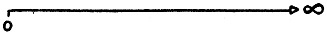
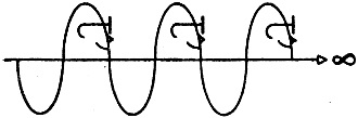
Transmission lines have always been a mystery to beginners in the RF field - both to newly branded engineers and to hobbyists and technicians. Many magazine articles on the topic have been written over the decades, and this one from a 1952 issue of Radio-Electronics is as good of a primer as any I have seen. Author Hector French incorporates many visual aids (aka drawings) to assist the uninitiated transmission line student grasp the concepts of impedance matching, standing waves, power transfer, etc. The only math in the entire article is characteristic impedance = voltage / current, and it does not include any scary talk about complex numbers with real and imaginary parts. BTW, it took me a moment to figure out that the objects added to the sinewaves are glasses, a nose, and a mouth to indicate a face looking in the direction the wave is moving. Transmission Lines Simplified Like one-way streets, they're fine if they take you where you're going - but watch out if you have to turn around! By Hector E. French It's usually easy enough to take electrical energy from one place to another - all that's needed at low frequencies is some wire for a conductor, and Ohm's law to figure out what is going to happen. But at high frequencies, Ohm's law seems to be a failure. The voltages and currents do all sorts of queer things along the line, and we don't find it easy to visualize what's really happening. But it's really not too difficult. Watch. First, imagine a transmission line that reaches out to infinity, and apply a signal to the line.
The ratio of the voltage to the current is the characteristic impedance of the line,
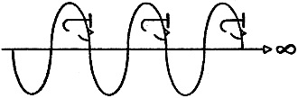
and if the line has no losses, both the voltage and the current can keep going forever
without dying out. And no matter how far or how long the signal travels, it will continue to see ahead of it the same identical value of characteristic impedance. Which is a monotonous situation indeed. So to break up the monotony, imagine that you're located somewhere out in space along the line a couple of million miles ahead of the oncoming signal
and cut the line.
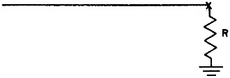
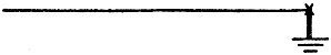
Now connect a resistance between the cut end of the line and ground, with the value of the resistance exactly equal to the characteristic impedance of the transmission line.
(Don't ask where the ground comes from - it's like learning to play chess.) Not too many seconds later, the signal will come whooping up the line at just a little less than the speed of light, and will run up against the resistance.
To the approaching signal, the resistance will appear to be just a continuation of the line, because the terminating resistance has exactly the same value as the characteristic impedance of the line. So all the signal energy flows down back into the ground through the resistance and is dissipated as heat.
And that's all there is to that side of the picture.
This is what is called a properly terminated transmission line. All the energy pumped into one end of the line goes directly through the load at the other end, assuming no losses in the line. The only requirement is that the load impedance be the same as the line's characteristic impedance. A good example is a transmitting antenna whose feeders are correctly matched to the radiating element, or a receiving antenna whose feeders are correctly matched to the receiver. But this isn't the only possible way to terminate the line. What if the line were cut and no resistance load put on at all?
Then when the signal gets to the unloaded end of the line it can't go any farther.
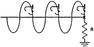
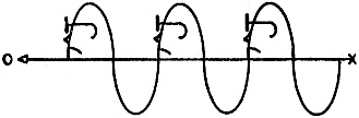
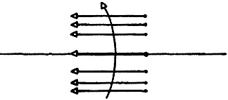
The only conductor available is the one that brought the signal away out here to the end of the line - so the transmitted signal does the only thing it can do. It promptly turns around and goes back along the same line, like a
reflection - back toward the beginning of the line. The trouble is, this reflected signal is on the same line at the same time as the transmitted signal. And the combination
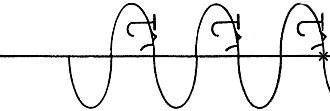
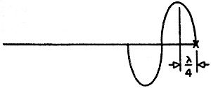
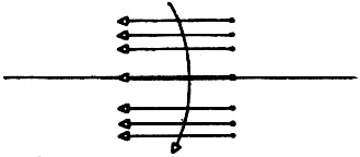
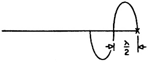
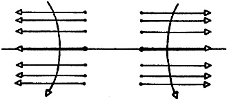
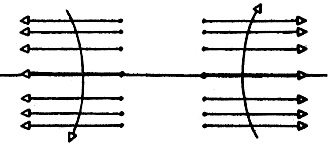
starts to look like a very confusing situation. But it's not as complicated as it looks. To see how easily the system can be analyzed, watch what happens to the voltage at the end of the line. This end is completely open. Nothing there at all to hold down the voltage. So, at the end of an open-circuited transmission line, the voltage is a maximum. This shouldn't be so very difficult to remember. Why shouldn't the voltage at the end of an open line be at a maximum - what is there to stop it? To analyze another point on the same line, simply back up from the end of the line by a quarter wave
and watch what happens to the voltage at this point as the transmitted signal goes by. Just like any other a.c., the voltage at this point will go negative,
and positive,
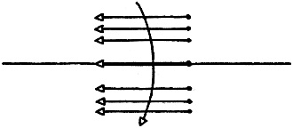
and keep on repeating the cycle as long as there is any transmitted signal. Now watch what is happening to the reflected voltage at the same point. This reflected voltage will be going through the same cycle as the transmitted voltage, obviously enough. But the reflected voltage is going positive
when the transmitted voltage is going negative, and the reflected voltage is going negative
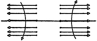
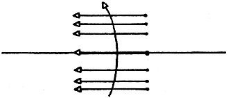
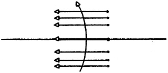
when the transmitted voltage is going positive! So whether the combined voltages at the quarter-wave point are considered like this:
or this:
the two voltages will always be in opposition and will balance out to zero. Therefore, at a point a quarter wave back from the end of an open-circuited transmission line the voltage is always zero. This surely differs from a conventional a.c. circuit - here is a point along a hot line where there is zero voltage! Now back up from the end of the line by another quarter wave,
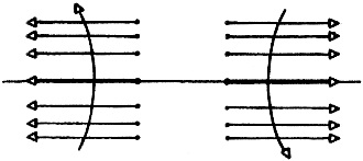
(making it a half wave from the end), and watch what happens to the voltage at this point. The reflected voltage this time is going positive
when the transmitted voltage is going positive, and the reflected voltage is going negative
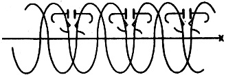
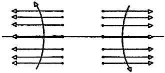
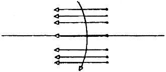
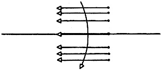
when the transmitted voltage is going negative. So whether we look at the combination like this
or this
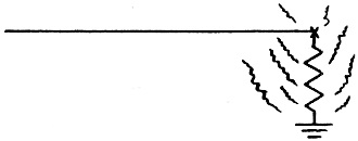
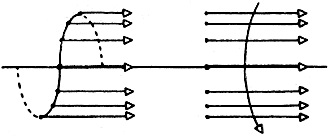
the two signals will always be aiding each other. Therefore, a half wave back from the end of an open circuited transmission line the voltage is a maximum. Just the same as it was at the very end of the line. If these measurements are repeated at quarter-wave intervals along the line, the same sequence repeats, giving points of maximum voltage along the line with points of zero voltage between them. This is known as a system of standing waves, and it is possible to make a general statement for the whole system: with an open-circuited trans-\mission line, at all even-numbered quarter waves from the end the voltage is a maximum, at all odd-numbered quarter waves the voltage is zero. Plus, of course, the very end of the line, where the voltage is a maximum also. Now there's still one more thing that can be done with this transmission line. Instead of leaving the cut end open, it can be short-circuited to ground.
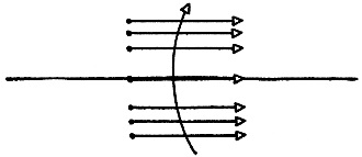
Don't ask where I got the ground this time, either- it's still like learning to play chess. There's no problem at all this time with figuring out the voltage at the end of the line. There's a dead short to ground, so, at the end of a short-circuited transmission line the voltage is zero. Now back up from the end of this short-circuited transmission line by a quarter wave, just as was done before. At this point, both a transmitted voltage and a reflected voltage will be present, just as in the open-circuited case. But this time the reflected voltage is going positive
when the transmitted voltage is going positive, and the reflected voltage is going negative when the transmitted voltage is going negative
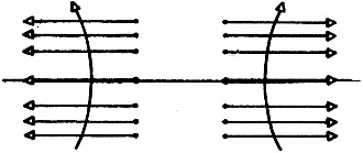
when the transmitted voltage is going negative. So whether we look at the combination of voltages at this point like this:
or this:
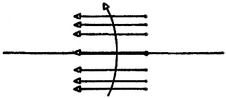
the two signals will always be aiding each other. Therefore, a quarter wave back from the end of a short-circuited transmission line the voltage is a maximum. Now back up along the line from the end by another quarter wavelength, just as before. This time the reflected voltage at the new point is going negative
when the transmitted voltage is going positive, and the reflected voltage is going positive
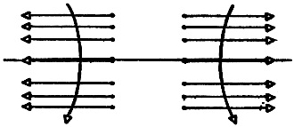
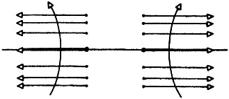
when the transmitted voltage is going negative. So whether the combination is viewed like this:
or this:
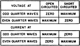
the two signals will always be in opposition and balance out to zero. Therefore, a half wave back from the end of a short-circuited transmission line the voltage is zero. (You may ask: "Why is any signal reflected from a grounded-end transmission line? It is easy to understand reflection from an open-ended line - the electrons pile up and - having nowhere else to go - come back along the line. But why doesn't the signal just run into ground and disappear?" The answer is easy. We have very large currents at the end of the line - the type we might expect at a short-circuit. These create a tremendous magnetic field around the line. When the signal has gone, the field collapses, producing a current that travels back along the line.) With this short-circuited transmission line, a system of standing waves is found, similar to the open-circuited transmission line. And a similar general statement can be made: with a short-circuited transmission line, at all even-numbered quarter waves from the end the voltage is zero, at all odd-numbered quarter waves the voltage is a maximum. Plus, of course, the very end of the line where the voltage is zero. The process for current is identical with that for the voltage, so there is no purpose to repeating the same details over again. The whole business can be put in one simple table:
That's all there is to getting a picture of what is happening along a transmission line. When properly terminated, all the energy in the line goes into the load with no reflection. But when the line is either open-circuited or short-circuited, a reflected signal is present which aids the transmitted signal at some points, and opposes the transmitted signal at other points. This reflected voltage travels all the way back to the generator at the beginning of the line - but that's a complete story in itself, for another time.
Posted December 13, 2021 |
|||||||||||||
 |
|||||||||||||
|
|||||||||||||


|
||||||||||||||||||||||||||||||||||||


