|
April 1968 Radio-Electronics
 [Table of Contents] [Table of Contents]
Wax nostalgic about and learn from the history of early electronics.
See articles from Radio-Electronics,
published 1930-1988. All copyrights hereby acknowledged.
|
Take a look at the
variation in antenna design in the 1960s as presented in Radio-Electronics
magazine. There was a boom in television
and FM radio happening at the time, and antenna manufacturers were coming out
with great new designs that promised to squeeze out that last little bit of
signal reception and interference rejection. While fundamentally most of the
antennas featured
the standard array of straight, constant diameter reflector and radiator
elements, many also incorporated fancy flat metal patches, spirals, and what
resemble modern printed elements without the substrate. My guess it was mostly a
combination of marketing hoopla and an effort to avoid patent infringements.
There are not many TV and FM radio antenna models available today, but those
that are generally don't have all the extra features. Some of the modern
compact TV antennas made for receiving
digital signals sport some fancy stuff, but they are fundamentally log periodic
or Yagi design. Ham antennas typically do not have all the extra gimmicks,
either. Aside from that, I have to acknowledge the amount of effort that went
into illustrating all 30 of these antennas. An EM analysis of each using the
latest modeling software would be interesting in order to see how they compare
to each other, and especially whether the special features made any difference
(perhaps even degrading performance).
TV/FM Antennas Are Getting Bigger and Better
 How to select the model for your need How to select the model for your need
The receiving antenna is a vital link in any wireless communication system. Acting
as a generator, the antenna intercepts waves traveling through the air, converts
them to electrical energy, and feeds them to the receiver.
It is primarily the antenna that determines signal quality. Later amplification
can increase signal strength, but it cannot improve signal quality.
All Channel TV/FM Antennas
|
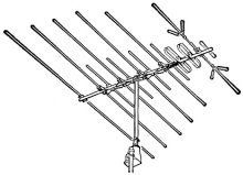
Channel Master Color Crossfire series utilizes
Vutronic design with colinear directors serving both uhf and vhf sections. The uhf
section uses series-fed dipoles with whiskers, while the vhf section uses the crossfire
principle. Mechanical features include blue Kralastic insulators at all crossover
points. vhf/uhf band splitter included. Model 3665-G shown has 13 elements.

Finney Color Spectrum series is "Frequency Dependent,"
providing higher gain at higher frequencies. Features square boom, one piece drive
line and insulated crossover spacers. Complete with uhf/vhf splitter. The model
CS-B2 shown has 6 driven vhf TV and FM elements, 10 driven uhf elements, and 3 parasitic
elements.
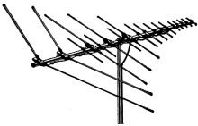
Gavin Gold Crest series designed on V-Yagi principle
for increased gain with flatness. Both uhf and vhf elements are combined into one
integral antenna. Features total weatherproofing, Cycolac insulators, reinforced,
heavy-duty aircraft aluminum elements and corrosion-resistant coating. Complete
with uhf/vhf TV/FM signal splitter. Model 1118 has 8 driven and 10 parasitic elements.
|
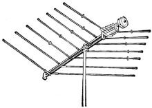
JFD Color Laser series uses frequency-independent
log-periodic V design with elements working on both fundamental and harmonic modes.
Resistance-loaded vhf dipoles with capacitance-loaded dual-band directors. Disc-on-rod
uhf directors. Includes uhf/vhf splitter. Twin boom construction. Model LPV-CL400
shown has 21 elements.
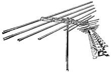
Jerrold Uses log-periodic design with hinged
joint, allowing separate uhf and vhf orientation. Square-boom construction, Cycolac
insulators and golden armor coating for ruggedness. Includes outputs for both 75
and 300 ohms. Model PXB-50 shown has 4 driven and 2 parasitic vhf elements, plus
11 driven and 16 parasitic uhf elements.
|
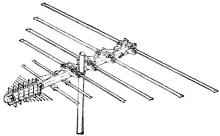
Lance Colormaster series use log-periodic design.
Features air-insulated crossover spacers, square-boom construction and automatic
locking hardware. Complete with uhf/vhf signal splitter. Model LC41 shown has 11
uhf elements and 6 vhf elements.
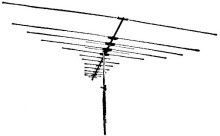
RCA Colorscan series uses modified Yagi design
for both uhf and vhf. The vhf portion utilizes multiple, exponentially tapered elements
of closely spaced end-fire type, coupled by folded transmission lines. Tuning stubs
are used on some of the directors to make them operate in both high and low vhf
bands simultaneously. The uhf portion utilizes full-wavelength dipoles. Round boom
construction and double polymerized vinyl coatings on all elements. Model 10B1120
shown has 14 elements.
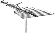
Wineguard Super Colortron series features built-in
housing for downlead, preamp, trap or filter. Ellipsoidal boom, high tensile aluminum
elements, and high-impact polystyrene wrap-around insulation. Complete with uhf/vhf
signal splitter. Model SC82 has 27 elements.
|
The radio antenna has evolved from an elaborate outdoor rig, to an indoor wire,
to a small ferrite loop inside the receiver cabinet. For a time, it seemed that
the television antenna was headed in the same direction. However, color TV, uhf,
FM stereo and CATV have all contributed to a reversal of the trend. The recent introduction
of the US Air Force Sub-miniature Integrated Antenna not-withstanding, the typical
1968 antenna is bigger and more efficient than ever before.
VHF/FM Antennas
|
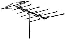
Channel Master Color Crossfire series uses "folded
whiskers" to make directors work on all vhf TV channels plus FM. They feature blue
Kralastic insulators and golden E-P-C coating. The model 3614 shown has 11 elements.
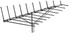
Finney Color Spectrum series features frequency-dependent
response (to compensate for unequal propagation of TV frequencies), one-piece drive
line, insulated crossover spacers and square boom. Model CS-V10 has nine driven
elements and one parasitic element.
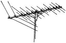
Gavin Gold Crest series utilizes V-Yagi design
for extra gain and flatness. Features round boom, reinforced, heavy duty elements,
Cycolac insulators and reinforced rivets. Model 1023 has 7 driven elements and 12
parasitics.
|

GC Electronics Magic Color series are designed
for use in the 60- to 100-mile range, have Gold Guard Finish for all-weather protection
and longer service life. Model 32-709 shown has 9 elements and a vhf TV and FM range
of 100 miles.
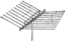
JFD Color Log Periodic series uses reactance-loaded
dipoles for narrower beams and dual band directors enabling elements to be active
for both high and low bands. Features twin boom construction and improved 300-ohm
impedance match. Model LPV-TV 100 shown has 10 elements.
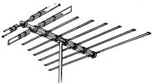
Jerrold Para Log Plus series features log-periodic
design plus Bi-Modal directors for extra gain. Square boom construction, Cycolac
insulators and golden armor coating provide ruggedness. Outputs for both 300 and
75 ohms included. The model PIX-75 shown has 8 elements plus 2 Bi-Modal directors.
|
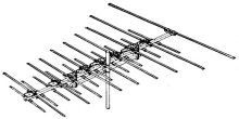
Lance Colormaster series features log periodic
design, square boom construction and automatic locking hardware. Model LC23 shown
has 19 elements.
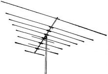
RCA Stratobeam series uses modified Yagi design,
with multiple, exponentially tapered driven elements of closely spaced end-fire
type, coupled by folded transmission lines. Some of the directors employ tuning
stubs to make them operate at both high and low vhf bands simultaneously. Features
include round boom construction and double polymerized vinyl coating on all elements.
Model 10B1020 has 10 elements.
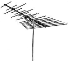
Wineguard Super Colortron series include built-in
weatherproof housing for twin lead or plug-in preamplifiers, filters or traps. Features
electro-lens director system and impedance correlators. 300- and 75-ohm outputs.
Model SC-53 shown has 20 elements.
|
Color TV has been the prime motivating force in the development and use of bigger
and better antennas. A recent poll showed that color TV was the "most wanted" item
of a majority of American women. Most people know that color is harder to receive
than monochrome. They are willing to invest in an antenna that will feed an expensive
new color set properly.
With more and more stations coming on the air and more and more people owning
all-channel receivers, the demand for uhf and 82-channel antennas has grown tremendously.
The growth of FM stereo has also led to more and bigger rooftop antennas. Good
FM stereo reception requires more RF signal at the tuner than does monophonic. This
often means more antenna gain. Hence, those interested in FM stereo generally buy
either a high-gain FM - only antenna or a good combination TV-FM antenna.
Gain is the factor most often used in comparing antennas. Actually, it is a misleading
term, since no antenna amplifies incoming signals. However, some antennas do produce
more signal voltage at their output terminals than others; gain is used to compare
two antennas.
UHF Antennas
|
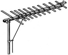
Finney Color Spectrum series utilizes log-periodic
design. Feature frequency-dependent response for higher gain on higher channels.
Model CSU2 shown has 10 driven elements and one parasitic.
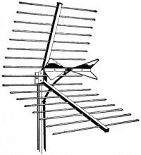
Gavin Gold Crest series utilizes bow ties with
corner reflectors to provide large vertical capture area and high gain. Easily added
to existing vhf antenna installation. Model CR-10 shown has one driven element and
16 parasitics.
|
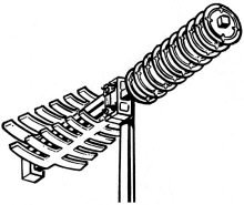
JFD Uhf Color Laser series uses log-periodic
design with disc-on-rod directors. Circular directors increase capture area. "Zoned"
log-periodic driver increases gain especially at low end of uhf band, where most
stations are. Model LPY-UCL22 shown has 6 driven elements and 10 disc-on-rod directors.
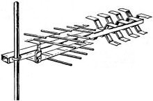
Jerrold Parapro series uses log-periodic principle,
plus directors for high gain. Easily added to existing vhf installation, without
need for special uhf/vhf coupler. Model PUX-450 shown has 11 driven elements, plus
8 directors.
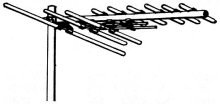
Kay-Townes Add-A-U series features Yagi design
and gold, corrosion-resistant finish. Easily combined with any vhf antenna. Model
AAU-9G shown has 9 elements.
|
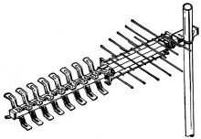
Lance Colormaster series uses log-periodic design.
Combines easily with vhf antennas, without uhf/vhf coupler. Model LU820 shown has
11 driven elements and 16 parasitic directors.
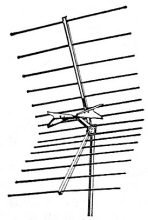
RCA Stratostar series is corner reflector type
with bow-tie driver. Large vertical capture area; 100° angle. Reflector
rods are permanently locked into support arms without holes or rivets, gold
anodized for corrosion resistance. Model 7B141 shown has a broadband 300-ohm dipole
and 15 tuned reflector elements.
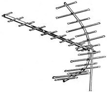
Wineguard Color Tracker series combines parabolic
reflector with Yagi. Large vertical capture area. Ellipsoidal boom. Model U-630
has 31 elements.
|

Fig. 1 - The half-wave dipole is the usual standard for comparison
of various types of antennas for TV and FM.
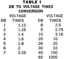 Common practice in using gain as a figure
of merit is to employ a half-wave dipole (Fig. 1) as the reference antenna. (An
open dipole has a nominal impedance of 72 ohms at its design center frequency; a
folded dipole has nominal impedance of about 300 ohms.) This dipole is said to provide
unity gain, or 0 dB (Table I). If an antenna produces twice as much signal voltage
at its output terminals as a standard half-wave dipole (when both are in the same
amount of RF field) the test antenna has 6 dB gain. (6 dB = 2 X voltage, as shown
in Table 1.) Common practice in using gain as a figure
of merit is to employ a half-wave dipole (Fig. 1) as the reference antenna. (An
open dipole has a nominal impedance of 72 ohms at its design center frequency; a
folded dipole has nominal impedance of about 300 ohms.) This dipole is said to provide
unity gain, or 0 dB (Table I). If an antenna produces twice as much signal voltage
at its output terminals as a standard half-wave dipole (when both are in the same
amount of RF field) the test antenna has 6 dB gain. (6 dB = 2 X voltage, as shown
in Table 1.)
FM Antennas
|
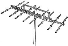
JFD LPL-FM series uses log-periodic design.
Features include full wavelength dipoles, controlled capacitance, excellent 300-ohm
match and twin-boom construction. Model LPL-FM8A shown has 8 elements.
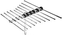
Jerrold Paralog series antennas work on log-periodic
principle. Highly directional, with narrow forward lobe to minimize multi path distortion.
Model FMP-10 shown has 10 elements.
|
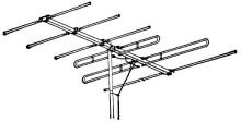
Finco FM series uses twin drive and impedance-match
stubs. Features include extra-wide element spacing, square-boom construction, corodized
aluminum elements and lock-tight saddle mounting. Model FM-4G shown has 2 driven
and 4 parasitic elements.
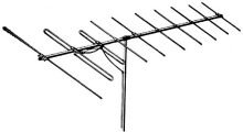
Gavin Color Crest series uses high-gain Yagi
design. Construction features include round boom, Cycolac insulators, internally
braced aircraft aluminum elements and corrosion-resistant plating on all surfaces.
Model FM-10 shown has 2 driven elements and 8 parasitics.
|
Metropolitan Antennas

JFD 82-channel log periodic model GK-4 is made
specifically to minimize ghosts in urban areas. Features "ISO-valve" trap to filter
out reflected signals. 6 vhf and 8 uhf elements, include splitter.
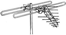
Jerrold Metro color series is designed to reject
reflected signals and minimize standing waves. Both uhf and vhf sections are hinged,
permitting separate orientation. Includes both 300- and 75-ohm outputs. Model MCX-82
shown has two vhf elements and 11 uhf elements.
|
Unfortunately, it's very hard to know just how much gain a given antenna provides
at a given frequency. And some antenna manufacturers have given up specifying gain
because it got to be an exaggeration contest.
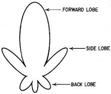
Fig. 2 - Older antennas, operating in 3/2 wavelength mode, had
large side lobes.
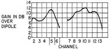
Fig. 3 - Older antenna response was not flat; they do poorly
with color sets.
If you really want to compare two antennas, put one up on a mast and then record
sound and picture carrier levels for each channel, as read on a reliable field-strength
meter. Then check the second antenna in the same way, installing it on the same
mast at the same height and aiming in the same direction.
Sad to say, even this seemingly foolproof method doesn't always work. In some
regions - especially weak-signal areas - signals vary from moment to moment. You
can actually watch the needle on your field-strength meter swing. Thus you can't
be sure that the incoming signal is the same for both antennas under test. But most
of the time this method will give you a pretty accurate estimate of which antenna
brings in the most signal.
One complicating factor is that antennas don't provide the same gain on every
channel. Some antenna manufacturers tilt their receiving antenna response, providing
higher gain at higher frequencies.
This brings us to another important factor - flatness. In the days of black-and-white
TV, the Yagi was king. It provided better gain than any antenna short of a parabolic
reflector. However, Yagis generally have two problems:
1. They operate at high frequencies in the 3/2 wavelength mode, resulting in
side lobes. And side lobes (Fig. 2) can pick up ghosts.
2. They don't have flat response.
Figure 3 shows the response of a typical Yagi. Notice that, within channel 6,
the response tilts by more than 5 dB. This generally causes no problem on black-and-white
TV. On color TV, however, the story is quite different. Not only is the color subcarrier
attenuated, but the response tilt causes changes in phase relationships. Since color
is detected in phase, this results in color distortion.
A couple of years ago, the log periodic antenna was popularized by JFD and the
University of Illinois. Admittedly, the log-periodic does not provide as much gain
as the Yagi (dollar for dollar or using a given amount of aluminum) but it is far
superior to the Yagi in flatness - so essential to color TV reception. Further,
engineers have overcome the problem of side lobes in the 3/2 wavelength mode by
"V"-ing the elements and by other ingenious methods.
Most major manufacturers now offer log periodics. (One exception is Gavin: they
claim to have modified the basic Yagi to provide flatness and eliminate side lobes
without sacrificing gain.)
A third factor in choosing antennas - and one that is often overlooked - is construction.
If you wish to avoid damage brought on by wind, snow, ice, corrosion, etc., be on
the alert for poor construction and structural defects.
How heavy are the elements? (Generally, the heavier the better.) Do the elements
make solid contact when they're snapped into place, or can they be wiggled around?
(Elements that vibrate in the wind may make and break contact, producing jumpy pictures.)
Are the elements reinforced? (Unreinforced elements may break off in the wind.)
Are insulators solid and nearly indestructible? Are the elements protected by a
corrosion-resistant coating? On larger antennas, are solid boom braces used?
The antennas shown here are only a sample of what's available for TV and FM reception.
Posted June 12, 2023
|


