|
August 1966 Radio-Electronics
 [Table of Contents] [Table of Contents]
Wax nostalgic about and learn from the history of early electronics.
See articles from Radio-Electronics,
published 1930-1988. All copyrights hereby acknowledged.
|
When I saw this 1966
Radio-Electronics magazine article titled, "Vibration and Shock - Nature's Wrecking Crew,"
for some reason the first thing I thought of was "The Wrecking Crew,"
that anonymously played the music for a huge number of popular singers - mostly
those without prominent bands of their own (Sonny & Cher, The Mammas and the
Pappas, The 5th Dimension, Simon & Garfunkel, and others - see
video) - during the
1960s and 1970s rock-and-roll era. ...but I digress. My introduction to the
potential deleterious effects of vibration on electronics was in the 1970s, with
airborne receivers and servos in my radio controlled model airplanes. Even
though they were transistorized (vs. vacuum tube types from a couple decades
earlier), vibration from glow fuel internal combustion engines (ICE)
could wreak havoc with potentiometers in servos and solder joints
everywhere, including battery packs. I remember seeing the control surfaces
(rudder, elevator, ailerons) jitter as the servos driving them jittered at some
engine RPM points. Usually, packing the receiver and battery pack with foam, and
mounting the servos with rubber grommets under the mounting surfaces mitigated
the issue. A lot of R/C airplanes have bit the dust due to vibration problems.
The systems are much better nowadays, and a majority of models are powered by
brushless motors, so most vibration sources are gone. My next memorable
experience was with the mobile vacuum tube airport search and precision approach
radars I worked on in the USAF. Nearly every time we packed up the trailers and
convoyed them to a new location, upon setting back up and going operational we
would find failed tubes and/or tubes that had vibrated partly out of their
sockets. This article delves into methods and equipment used to investigate
vibration and shock effects on electronics.
Vibration and Shock - Nature's Wrecking Crew
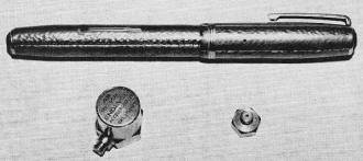
Fig. 1 - Two typical piezoelectric accelerometers. Most units
mount with studs or cement.
By William F. Kernin*
In controlled usage, vibration and shock are powerful and beneficial tools of
nature. If they are uncontrolled - all havoc breaks loose. The random shock forces
encountered by a ballistic missile, for example, exert tremendous loads on the electronic
circuitry packed inside the "bird." Combined with ever-present vibration fields
due to specific-impulse and frictional factors, these spurious effects do plenty
to shake up - sometimes even destroy - the "black boxes."
To investigate these forces and design electronic equipment to survive them,
the intensity and specific characteristics of the vibration and/or shock must be
defined. That is where the vibration pickup and its associated electronic instrumentation
play their roles. Let's examine typical equipment used to analyze these two very
similar effects and determine how we can use it to de-fine and catalog our twin
topics.
The most common device used to transform mechanical motion into an equivalent
electrical signal is the piezoelectric crystal accelerometer. Fig. 1 shows two general-purpose
devices suitable for many applications. Basically, a pickup of this type consists
of a piezoelectric crystal which is mechanically preloaded, using a spring-and-mass
arrangement. Any movement in the sensitive axis of the pickup causes a variation
in its electrical output. The signal obtained from the pickup is fed to a companion
amplifier by means of a low-noise, single-conductor shielded cable.
Various amplifiers with very high input impedance are available commercially
for use with crystal accelerometers. One type uses a modified cathode-follower input
stage to produce an input impedance variable from 100 to 1,000 megohms, depending
on the circuit design and the user's selection of resistor values.
Fig. 2 shows a typical input stage and its associated amplifier circuitry. Because
input grid resistor RG is returned to ground through the cathode-load
resistor RL, the output-signal voltage is common to both input and output;
thus a large degree of feedback is obtained. The feedback level is great enough
to raise the input impedance from an expected value of 20 megohms, suggested by
RG, to a value of 200 megohms or higher. The actual impedance depends
on the value of grid resistor RG and the overall gain of the cathode
follower - a value always less than 1. As gain approaches 1, the input impedance
rises to a very high value. Very high input impedances are necessary because the
crystal accelerometer is a high-impedance voltage-producing device. It must be lightly
loaded to maintain its sensitivity and response to low frequencies.
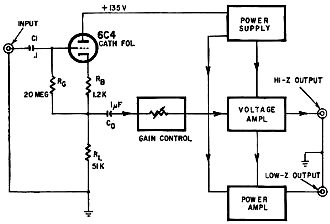
Fig. 2 - Cathode follower provides very high input impedance
for accelerometer amplifier.
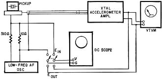
Fig. 3 - Setup for checking overall response. Scope or vtvm can
be used for measurements.
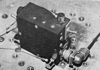
Fig. 4 - Vibration is checked in tree planes by pickups on top,
side and rear of equipment.
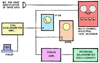
Fig. 5 - A typical instrumentation setup. Recorders preserve
records for later analysis.
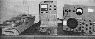
Some of the equipment used to monitor and record vibration data.
Industrial recorder is on the left, seven-channel FM recording amplifier and meter
are in center. On the right is a dc oscilloscope and power supply. Pickup transducer
is at front of table.
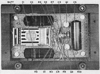
The simplicity of the scope switch is indicated in this under
chassis view.
A gain control and voltage amplifier follow the input stage, allowing low-level
signals to be boosted to a usable value. The output of this circuit then feeds indicating
instruments of somewhat lower impedances: an audio frequency vtvm, scope, or tape
recorder, for example. Also, this output can drive an additional power amplifier
that in turn drives a low-impedance recording galvanometer or other type of direct-writing
recording device.
To determine the frequency response of a cathode-follower/amplifier and its crystal
accelerometer - particularly at frequencies as low as 1 Hz or so - the setup shown
in Fig. 3 can be used. In this circuit, a 10Ω resistor is connected in series
with the pickup case. The combination feeds the input of the cathode-follower and
amplifier, feeding a nominal load. A low-frequency oscillator is connected across
the 10Ω resistor as shown, using a 510Ω series resistor. The dc scope
is used first to set the input level across the Ion load, then to measure the relative
output level for each frequency. Gain at 1 kHz is found first and used as a reference
level. Other frequencies can then be checked as desired to obtain a complete response
curve.
In a typical test setup used to measure environmental vibration levels, three
accelerometers are used - one for each plane (horizontal, vertical and lateral).
The pickups can be stud-mounted or cemented directly to the component under test.
In most cases, cement offers the best solution. Caulk Grip Cement - a dental product
- is a good, general-purpose adhesive that sets sufficiently strong for vibration
work in 30 minutes or so. For high-temperature work, as encountered on some points
of a rocket engine, Armstrong type A-1 adhesive may be used. Fig. 4 shows a typical
"black box" on which three accelerometers have been cemented prior to testing.
After mounting, each pickup is connected to its accelerometer amplifier through
low-loss cable. A small rubber washer on the connector helps prevent shaking loose
the cable. For high-humidity or altitude-chamber work, the connector is coated with
a liquid silicone rubber (General Electric RTV-20) that cures at room temperature.
When the test is over, the pliable rubber coating can be peeled off easily. As a
final precaution, the miniature cable from the pickup is taped down close to the
pickup and elsewhere along its length to prevent it from whipping around during
testing.
Depending on what use is to be made of the test signal, the output of each amplifier
can feed a scope, meter, tape-recorder channel, or recording oscillograph. Fig.
5 shows some equipment that may be used, singly or in combination.
Before a setup can provide meaningful data, the equipment must be calibrated,
beginning by finding the pickup sensitivity. For most purposes, vibration and shock
are measured in G's, one G being equivalent to normal gravitational force. The pickup
to be checked is mounted on a small shake table which will provide known variable
G forces. Its output is checked against that of a standard pickup - also mounted
on the table - at different frequencies. The sensitivity of the test pickup is then
expressed in millivolts rms per G peak.
Pickup sensitivity is affected by the characteristics of the cable connecting
it to its amplifier, by the amplifier's input capacitance, and by the pickup's internal
capacitance. Thus, complete calibration information may read like this for a typical
unit:
E (sensitivity) = 20 mV rms/G pk
C (pickup) = 900 pF
C (cable) = 87 pF (3 ft of cable)
C (amp input) = 23 pF
If, when setting up a test, a different length of cable is used, the pickup sensitivity
must be corrected using the following equation:

Thus, any convenient length of cable may be used and the calibration sensitivity
corrected correspondingly, as long as the cable capacitance and amplifier input
capacitance are known. The low-noise cables supplied with most pickups are normally
tagged with their total capacitance values.
Continuing our hypothetical calibration: If for a particular test the expected
level may reach ±10 G's, this suggests maximum possible signal of 10 x Erun
(200 mV rms, using the sample calibration data). Using an audio oscillator, a signal
of approximately 1 kHz is fed into the input of the accelerometer amplifier at the
expected 10-G level (200 mV rms). The amplifier gain control is then adjusted for
some convenient output value - 1 volt on a vtvm, 10 scale divisions on a scope,
the maximum acceptable input for a tape recorder, or 2-in. deflection on the recording
oscillograph. The system has then been calibrated so that a level of ±10
G's peak seen by the pickup will produce an easily read, known output. All pickup
channels are calibrated this way, and the system is ready to go.
There are any number of applications for an accelerometer system in the measurement
of vibration and shock levels. For example, the system can be used to obtain vibration
information from apparatus under actual operating conditions, as in the recording
of vibration levels on a rocket engine during hot-test firing. In actual tests of
this type, multi-channel tape recorders record highly varied vibration data ranging
from dc signals to high-frequency vibrations. A permanent record of the rocket test
run is obtained on tape, and it can be reduced, analyzed or transformed into any
form desired.
Vibration-Inducing Devices
After actual operating or environmental levels are determined, much vibration
testing is concerned with applying G forces to components, black boxes, and systems
at known levels to reveal any defects, or to quality the equipment.
A common instrument used for such testing is an electrodynamic vibration exciter.
This type of shaker consists of a massive driver - a voice-coil-driven table-field-coil
arrangement. It is powered by high-energy amplifiers or a controllable, variable-speed
motor-generator set. Equipment to be tested is mounted on the shaker head. Standard
pickups are then mounted on the device under test so that forces applied can be
recorded and used later for reference or evaluation.
A more elaborate type of shaker is the random-vibration machine. Instead of steady
frequencies, this instrument employs a band of frequencies with no definite repeatability
characteristics-random noise - to drive a specially designed shaker head through
powerful amplifiers. Failures often show up during random-noise tests that might
never be discovered in steady frequency tests. (See "Big Noise", Radio-Electronics,
Aug. 1963.)
Maintenance on vibration test equipment is basically a matter of common sense.
The pickup should be kept clean to afford good mechanical contact; the connector
must also be clean as possible. The miniature cables are tough, but no undue strains
or sharp bends should be allowed, especially at the connector ends. Avoid excessive
temperatures near the pickup. To shield a pickup from a nearby radiating heat source,
several layers of shiny aluminum foil have proved quite helpful as a rough reflective
cover. The cathode-follower/amplifier circuitry is not complex and can be serviced
with standard signal-tracing techniques when trouble develops. To insure optimum
operation and accuracy, the pickups and associated circuitry should be calibrated
as often as possible; once a month is considered adequate.
While the typical industrial electronics technician may seldom see much vibration
testing equipment, he should be aware of the basic principles and circuitry involved.
Not only may this information come in handy when he does encounter such devices,
but it may lead to further study and open new areas of new business through direct
contact with those actively engaged in vibration testing.
* Instrumentation technician, Engineering Labs, Bell Aerosystems Co., Division
of Bell Aerospace Corp., Buffalo, N.Y.
|


