|
|||||||||||||
 |
|||||||||||||
What VSWR Does to Your Communications
|
|||||||||||||
Veterans of the RF communications realm are well aware of the detrimental effects of not properly impedance matching all components in a transmit-receive chain. The most common impedance used is 50 Ω pure resistive (50+j0 Ω) in nature, and when the input and output impedances are all at that value, power is transmitted without reflection (100% efficient). Except for optimal power transmission purposes (other impedances optimize values other than power), any impedance can be used, including those with imaginary parts (capacitive or inductive). In that case, the requirement for no reflection is that the load of each stage in the chain be the complex conjugate of the source (i.e., if Zsource = R0 + j0 Ω, then Zload = R0 - j0 Ω). This short feature in a 1966 issue of Radio-Electronics magazine reviews the matter. What VSWR Does to Your Communications
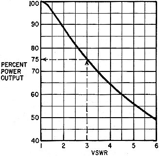
Fig. 1 - Percent of power output versus voltage standing-wave ratio. 100% is the rf output of the transmitter into a perfectly matched, nonreactive load. A voltage standing-wave ratio of up to 2:1 is not serious, but greater mismatching can rob you of expensive power By David L. Pippen* A Transmitter is normally designed to work into a particular load impedance. An antenna is designed to be driven by a transmitter with a particular output impedance. Likewise, the transmission line used to connect the transmitter to the antenna should have a characteristic impedance that will match the antenna and transmitter impedances. That, in a nutshell, is what this business of matching transmitter to line to antenna is all about. If they are matched, the signal generated by the transmitter will be sent along the transmission line and applied to the antenna with maximum efficiency. The antenna can then radiate practically all the signal into space. If there's a mismatch in the system, the energy traveling toward the antenna will be reflected and cancel the "fresh" energy from the transmitter at regular intervals along the line. Now, maximum and minimum voltage (and current) points exist on the transmission line; no longer can we open the line at any point and find the same rf current in it as at any other point. In radio parlance, the line is no longer "flat". The ratio of maximum voltage to minimum voltage is a measure of system impedance matching and is called the voltage standing wave ratio, or VSWR. A VSWR reading of 2:1 (or just "2") implies that there is a system impedance mismatch ratio of 2 to 1.
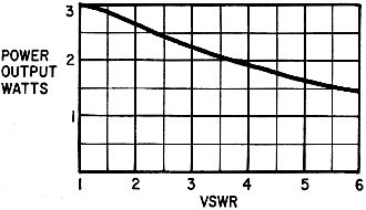
Fig. 2 - Actual power output in watts of a 3-watt system with various VSWRs. This curve is handy for figuring the power out-put of CB transceivers. VSWR meters for most frequencies are readily available and are an easy way to determine how well the parts of a particular system are matched. But, though the VSWR meter gives valuable information, it doesn't give much of a feel for just how badly a system's performance can fall off at various VSWRs. So let's try a different approach. Figs. 1 and 2 are graphs that can tell you at a glance how much power will be lost by a particular mismatch. To use Fig. 1 for a particular system, measure the rf power output of the transmitter connected to a matched resistive load (many power meters use a resistive load), then measure the system VSWR with the transmission line and antenna connected. This information, with the graph of Fig. 1 and a simple calculation, will indicate power loss due to the VSWR. As an example, suppose the measured rf power of a transmitter is 100 watts. The VSWR reading indicates 3 to 1. Find the VSWR of 3 on the horizontal axis of Fig. 1 and then move upward until you meet the curve. Then move to the left horizontally and read the percent power output (75% in this case). Now multiply the transmitter power by the percentage figure to obtain the reduced power output (100 X 0.75 = 75 watts); the 25-watt loss is caused by the VSWR. So a VSWR of 3 causes a loss of 25% of the power a system could deliver with a VSWR of 1. A VSWR of 2 causes approximately 11% power loss, or about 0.5 dB. That's the generally accepted maximum VSWR for a system. The ideal system is, of course, 1:1. For CB operators, there's Fig. 2. Most good CB radios can put out approximately 3 watts of rf for 5 watts of dc input. Therefore, by using Fig. 2, you CB'ers can calculate close to your actual effective power output for a particular VSWR. If you need a more accurate indication, calculate from Fig. 1, using the actual power output of the transmitter as previously explained. * Manager, Electrical Measurements and Standards Laboratory, NASA-White Sands Test Facility, N. M. |
|||||||||||||
 |
|||||||||||||
|
|||||||||||||


|
||||||||||||||||||||||||||||||||||||


