|
|||||||||||||
 |
|||||||||||||
Weather Radar Makes Flying Safer
|
|||||||||||||
Once upon a time, long, long ago, I believed that someday I would be a military pilot for a couple decades, then retire and work for the airlines. Eagle eyesight (20/15) and very good health, two prime requirements for the USAF to permit guys to fly their multimillion dollar airplanes, were not enough. A college degree in engineering or science must be possessed as well. I enlisted in the Air Force (1978) with plans to earn a degree during off-duty time. Having begun flying training prior to entering, I figured working as a technician on weather equipment would be a good gig whilst earning that sheepskin. Turns out my "guaranteed" job was not really available, so after threatening to take Uncle Sam up on his contract point allowing me to go back to civilian life if the USAF reneged, I refused the alternative clerical career options and accepted an Air Traffic Control Radar Repairman (AFSC 303x1) job. It turned out well, but the mobile communications squadron I was assigned to made taking college courses nearly impossible. So, after a four-year stint, I got out and graduate with a BSEE degree in 1989. This article encompasses two of my main interests - electronics and weather, although my radar experience was with ground-based rather than airborne radar. For the record, I never did get even my Private Pilot license - needed only the check ride just prior to reporting for Basic Training, but the rotten November weather prevented it. Then, at $419/month E-1 pay, I couldn't afford to fly. Life interfered in various ways beyond that obstacle. Are you bored with my waxing nostalgic yet? Weather Radar Makes Flying Safer
C-band and X-band radar systems pinpoint storms and turbulences. By Donald E. Bowen Weather is probably the most important factor in flying safety. A world-wide network of meteorological stations furnishes information on weather conditions continuously. But local weather conditions can change so rapidly that this information is not enough to keep a pilot informed of all weather conditions in the immediate vicinity. By using weather radar equipment, the pilot actually sees an accurate and continuous "picture" of weather conditions ahead of the aircraft-a weather map. The weather map shows the location of weather fronts in terms of range and azimuth bearing, relative to the position of the aircraft. It identifies potentially dangerous areas such as thunderheads, hailstorms and turbulence. With this map as a guide, a pilot can navigate to avoid storms or turbulent areas, often by detours of less than 5 miles from the planned flight path. Radar Weather Observation To observe and interpret weather on a radar system, it is necessary to understand the display on the indicator screen. The radar information is presented on the face of a cathode-ray tube. The mask on the tube face is set up in terms of range and azimuth. The sweep trace on the tube rotates in synchronism with the radar antenna mounted in the nose of the aircraft. For both range and azimuth determination, bottom-center of the screen (upper portion of Fig. 1) represents the position of the aircraft. The 0° calibration represents the heading. All echo returns (reflected energy) appear as brightened areas on the screen, displayed to the left or right of the 0° reference, depending on the object's position - left or right, respectively, of the aircraft (Fig. 1). Range marks (concentric circular traces at regular intervals on the screen) are set up as references in terms of distance from the aircraft.
Fig. 1 - Relative positions of aircraft and weather feature: actual (bottom) and as displayed (top). Bottom center of screen represents aircraft. Weather information detected and presented by the weather radar system is based on rainfall gradient: the variation of the rate of rainfall with distance. Radar pulses are reflected by precipitation, such as rainfall, wet hail or wet snow. Variations in rainfall gradient are detected by contouring (Fig. 2). When the radar is set up for contouring, areas of heavier rainfall appear as dark spots on the indicator screen, while the brighter display areas indicate lighter rainfall. Contouring The reason for this apparent paradox lies in the contouring system used. Since the brightness of the display depends on signal strength, agc cannot be used in this system - it would level off most of the amplitude changes in the return signal. However, the absence of age seriously limits the "dynamic range" of the radar. For a particular screen-intensity setting, there is only a limited discernible range of brightness variation. A return below this range would produce no image, while a return above it would saturate either the display tube or the amplifier, producing a bright spot that would not get brighter no matter how much further the signal increased. But since the return signal is a pulse whose amplitude is related to signal strength, we can solve the problem by reshaping the pulse. It is reshaped so that all returns below some predetermined level will be displayed in normal fashion (brightness directly proportional to strength of return), while all returns above this level will show as a "negative" of the area that causes the return (brightness inversely proportional to strength of return). Thus, the weak returns (as from the perimeter of a turbulent area) show on the screen in the normal way - dim around the edges, brighter toward the center. But when the return exceeds the preset level (as it would in return from a turbulence with a steep gradient), the display is reversed so that it becomes darker as the reflected signal increases. That leads to the kind of display labeled CONTOUR in Fig. 2. The fringe of the storm appears as a bright area (moderate return) that encircles the violent core of the storm, shown as a "hole" (strong return). Since contour presentation is not always desirable, the equipment has a switch to permit it to be used as normal radar.
Fig. 2 - Normal and contour display of weather front. Dark areas on contour display are turbulent "high-gradient" spots. How It's Used Meteorological studies show that violent turbulence occurs near steep rainfall gradients (where the change from no rainfall to heavy rainfall occurs in the shortest distance). When the radar is set for contouring, steep gradients are displayed on the radar screen as relatively large "cores" (dark areas) surrounded by a narrow ring of bright returns. If there are no cores (or only very small ones) surrounded by large, bright rings, there is little or no turbulence. Thus, the inner and outer edges of the bright returns which surround the dark cores are contours that approximate the rainfall rate. Obviously, the safest path for the aircraft is the path which avoids the dark storm cells indicated on the radar screen. A large thunderstorm area might contain not one but several individual storm cells, each in a different stage of development. The average life of a storm cell is about 1 1/2 hours. (Because the several cells vary in stages of development, local weather information only minutes old is almost useless.)
Collins WP-103 weather radar installed in cockpit of Beech Super 18-G. Indicator screen is centered on panel, controls are in bottom center of photo, between seats.
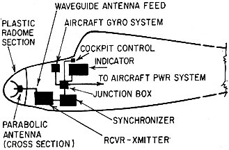
Fig. 3 - Typical arrangement for mounting weather radar components in a plane. (Relative sizes of components are exaggerated for clarity.) One of the most significant features of thunderstorms is vertical development. Generally, a thunderstorm will develop at some altitude between 8,000 and 15,000 feet. If the top of the storm goes beyond 30,000 feet, turbulence is likely. If the top passes the 40,000-foot level, especially in temperate latitudes, damaging hail and severe turbulence are imminent. When the top reaches 50,000 feet, tornadoes are extremely likely. Hail (associated with updrafts or downdrafts) or dangerous tornadoes are indicated on the radar by fingers, hooked fingers, scalloped edges or U-shaped projections extending from intense echoes (contoured). These projections are very dangerous, as is an overhang from a thunderstorm. The System Weather radar is like any of the familiar radar systems in use, the principal difference being its application. Special lightweight systems have been developed specifically for small commercial and privately owned aircraft. These systems may be divided into C-band (5,400-mc) and X-band (9,400-mc) systems. The C-band radar system is larger and bulkier, a result of the lower frequency, which requires larger waveguides, cavities and antenna systems. But C-band frequencies permit deeper weather penetration. Representative weather radar systems have three ranges: for example, 30, 60 and 150 miles. Markers for these ranges are typically 10, 15 and 25 miles. An antenna sweep of 60° either side of dead ahead is adequate. Systems are usually installed with the antenna in the nose of the aircraft, protected by a plastic radome which replaces the original nose section. (The radome is painted to match the finish of the aircraft.) To avoid long pieces of waveguide, the receiver-transmitter unit is frequently mounted near the antenna (Fig. 3). Of course, the cockpit control and indicator are mounted on the instrument panel, accessible to both pilot and co-pilot. Operating power and gyro signals for antenna stabilization are supplied from existing aircraft facilities.
Fig. 4 - Relationship between terrain below aircraft, and display, when radar is used for ground observation. (Left), "actual" river, with position of aircraft and scanned sectors. (A hove), how scene appears on indicator screen. A Complete System
This system is a pulse-modulated radar device that operates at 9,375 mc (X-band). The narrow beam of rf energy radiated at X-band frequencies de-fines the targets sharply. Short, high-powered pulses of rf energy generated by the transmitter are radiated in a narrow beam by the antenna located in the nose of the aircraft. The antenna sweeps from 60° left to 60° right, then back, 30 times per minute, taking a total of 60 scans per minute. When the rf energy strikes an object (such as a storm cell) within the 150-nautical mile range of the equipment, it is reflected to the antenna as an echo and applied to the radar receiver. The detected echo, a video signal, appears on the screen as a display of the object that caused the echo.
Major components of Collins WP-103 weather radar. Collins Radio Co. The synchronizer unit generates and controls the sweep trace and range circles. Indicator sweep trace and antenna sweep are locked together by the synchronizer to insure that echoes are displayed at the correct range and azimuth bearing. The "rest" trace on the indicator is a bright line which sweeps back and forth across the screen, representing the scan of the antenna. When an echo is received, the sweep trace is brightened (or darkened) on the screen, showing the range and azimuth of the weather target. A stabilized antenna system, together with the aircraft's gyros, compensates for pitch and roll. The weather-map presentation is in the same plane regardless of normal pitch and yaw of the aircraft. An additional feature of the stabilization system is variable antenna tilt, making it possible to map the terrain below and in the path of the aircraft (Fig. 4). Here, an aircraft is flying over a river at an altitude of 10,000 feet. The antenna is tilted to 6° below the horizon. Compare the indicator displays A, B and C with the river at scans P1, P2 and P3, respectively. The Collins WP-103 is available with a 12-, 18- or 30-inch antenna, and either a conventional or bright-tube indicator. Increasing the size of the antenna improves intensity and definition. The conventional indicator provides the familiar yellow offset display. The bright-tube indicator provides a brighter, longer-lasting display that enables the pilot to view the screen even in bright sunlight without a hood. An adjustable Polaroid filter dims the display for nighttime operation. The bright-tube presentation can also be varied from a normal yellow-green to red. Accuracy is not affected by the color change. Weather radar has been extremely successful in adding to the comfort and safety of airlines flights. Because of this, more and more executive airplanes, too, are being equipped with weather radar systems. Small, lightweight, relatively inexpensive units ideal for executive aircraft are available. You can certainly expect to see more and more of these systems in the near future. |
|||||||||||||
 |
|||||||||||||
|
|||||||||||||


|
||||||||||||||||||||||||||||||||||||


