|
January 1961 Radio-Electronics
 [Table of Contents] [Table of Contents]
Wax nostalgic about and learn from the history of early electronics.
See articles from Radio-Electronics,
published 1930-1988. All copyrights hereby acknowledged.
|
Zener diodes, named
after their inventor,
Clarence Zener, were a
paradigm-changing introduction to the electronics industry. At a very low price
and parts count, precise and stable voltage sources can be built for just about
any voltage reference level. Zeners are designed to operate in the breakdown region of
the pn junction which is normally avoided with standard rectifier diodes. That
voltage level is predictable and consistent. A standard range of voltages
(2.7 V, 3.0 V, 3.3 V, 3.6 V, 3.9 V, 4.3 V, 4.7 V, 5.1 V, 5.6 V, 6.2 V, 7.5 V, 8.2 V, 9.1 V, 10 V, 11 V, 12 V, 13 V, 15 V, 16 V, 18 V, 20 V, 22 V, 24 V, 27 V,
...) are
manufactured to satisfy most needs. Notice a familiar pattern there? Yep, they
follow the standard 5% tolerance
resistor value series. I don't know why that was done - there is no
semiconductor physics
reason for it. Just as having a standard 5x10n Ω value for resistance
would be extremely handy, so it would be for a voltage reference, given the
prevalence of 50 Ω for impedances and 5.0 V for digital circuits.
Zener Diodes Simplified - Zeners can do a number of jobs
better than can any present device.
 By Donald L. Stoner By Donald L. Stoner
Engineers and service technicians are constantly being showered with new electronic
components, many of which are too costly to ever appear in mass-produced equipment.
One exception is the Zener diode. These interesting devices were introduced some
time ago, but only recently have they become available to the budget-conscious experimenter.
This amazing member of the diode family is the solid-state equivalent of a voltage-regulator
tube. But the Zener diode takes over where the V-R tube stops (about 75 volts) and
is available in steps down to 3.9 volts.
In many respects, the Zener diode is also similar to the silicon rectifier cell.
Such rectifiers are rated according to their current-handling ability and peak inverse
voltage (or piv) the total or peak voltage appearing across the diode junction when
it is reverse-biased (negative anode). If this peak rating is exceeded, the effects
may be disastrous. If sufficient current flows to overload the diode in the reverse
direction, a multiplication or avalanche takes place within it. Designed to handle
only a few watts of power in the forward direction, it is subjected to many times
its rating by the excessive reverse current. When this happens, the silicon wafer
is overheated and the crystal structure destroys itself. A device damaged in this
manner shows a low resistance in either direction and is no longer useful as a rectifier.
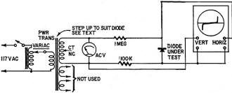
Fig. 1 - Circuit for testing peak inverse voltage of silicon
rectifiers.
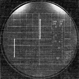
Typical Zener oscillogram for the equipment shown in Fig. 1.
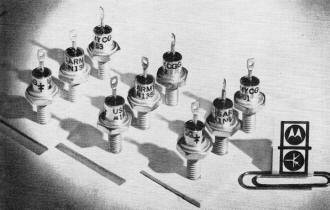
Zener diodes for military uses solve many electronic design problems.
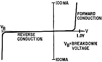
Fig. 2 - Current and voltage characteristics of typical Zener
diode regulator.

Fig. 3 - Basic Zener diode regulator.
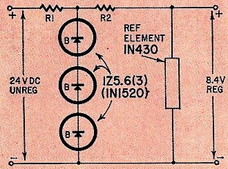
Fig. 4 - A very accurate voltage standard.
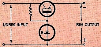
Fig. 5 - Simple regulated power supply.
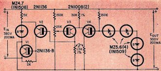
Fig. 6 - A 300-volt, 200-ma solid-state regulated supply.
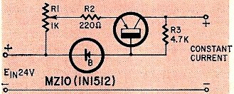
Fig. 7 - Constant-current regulated supply. Values shown are
for 10 ma maximum load current.
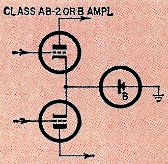
Fig. 8 - Zener-diode biased audio stage.
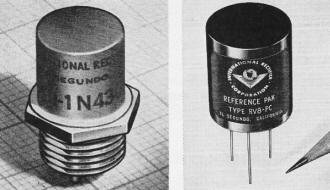
(L) International Rectifier USN-IN430 silicon reference element.
| (R) Miniature voltage reference pack contains all components shown in Fig.
4.
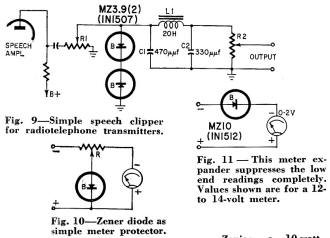
Fig. 9 - Simple speech clipper for radiotelephone transmitters.
Fig. 10 - Zener diode as simple meter protector.
Fig. 11 - This meter expander suppresses the low end readings
completely. Values shown are for a 12- to 14-volt meter.
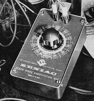
Zeniac, a 10-watt Zener diode substitution box made by International
Rectifier.
It is a common fallacy that exceeding the piv will ruin the diode. You can prove
this is an "old wives' tale" and incidentally make a handy piv checker by constructing
the circuit in Fig. 1. The series resistance prevents excessive current flow in
the silicon rectifier cell during reverse bias periods. The power transformer can
be any type that will put out about 800 volts. The picture displayed on the oscilloscope
is shown in the accompanying photograph. You can determine the piv by either calibrating
the base line of the oscilloscope or measuring it on the meter. If the meter is
used for measurements, it will be necessary to multiply the reading by 1.414 to
determine the peak value.
Zener Diodes
When forward-biased (positive anode), the Zener diode behaves much like the silicon
rectifier cell just described. Once the barrier potential (0.6 volt approximately)
has been overcome, the junction resistance drops to a low value and the diode conducts
large amounts of current. In the reverse-bias direction (negative anode), only a
tiny amount of current can flow. However, as the reverse voltage is increased, a
point will be reached where avalanche or breakdown occurs. When avalanche breakdown
is reached, the normally high back resistance drops to a low value and the junction
current is limited by the circuit resistance. As the voltage is increased beyond
the breakdown point, the diode current increases proportionately but the junction
voltage remains essentially constant as shown in Fig. 2. Although we might say that
the piv has been "exceeded," the diode is made large enough to dissipate the generated
heat without damaging the junction.
Let's see how this effect can be used in a practical application. Fig. 3 shows
a common method of connecting a Zener diode in a regulator circuit. The diode, in
shunt with the load, draws current through resistor R, which is in series with the
load. The total current through R is the sum of the Zener and load currents. If
the unregulated input voltage increases, the current through both the Zener element
and the load will increase. Simultaneously, however, the diode resistance decreases
and the junction current increases, thereby adjusting the voltage drop across resistor
R. Load variations have a similar effect on the diode regulator. As the load current
increases, or decreases, the Zener shunt element will draw less or more current
respectively. The net result is substantially a constant output voltage across the
load.
The ability to regulate voltage or load changes is determined by the temperature
coefficient and the dynamic impedance of the diode. A change in junction temperature
can shift the diode operating point. The dynamic impedance is something like a bleeder
resistor connected across a power sup-ply. The lower the dynamic resistance, the
better the regulation. Temperature affects the Zener diode least in units around
5.6 volts. The dynamic impedance is reduced in larger diode sizes.
The only unknown in Fig. 3 is the correct value for resistor R. The value can
be determined experimentally by substituting a rheostat for R and set-ting it so
the Zener diode draws 20% of its maximum current rating (the customary operating
point for a Zener diode).
The exact value can be calculated more accurately by using the formula:
R = (Ein - Ez)/(Iz + IL)
To apply this formula, let's work out a typical Zener regulation problem. Assume
you have a transistorized variable-frequency oscillator which operates in an automobile
and must be regulated. The oscillator draws only 10 ma; thus even the smallest Zener
units will be usable. We know that oscillator operation is satisfactory with a 9-volt
battery. Therefore a Zener unit near this voltage is selected. A short consultation
with the semiconductor catalog shows that an 8.2-volt 750-milliwatt, 1N1511, made
by International Rectifier Corp., should do the job nicely.
Once the diode ratings are known, we can calculate the value of R. The automobile
battery (Ein) will be approximately 14 volts (maximum) and Ez
is 8.2 volts. The maximum Zener current (always given in the diode characteristics)
is 90 ma, and therefore the normal operating point would be 18 ma (see above). All
the numbers required to fill in the formula are now known and it solves like this:
R = (14 - 8.2)/(0.018 + 0.01)
R =- 207 ohms
Either a 200- or a 220-ohm resistor may be used for R and the Zener current will
be slightly above or below the nominal operating point, but well within the diode
ratings.
The wattage of R can be determined easily, since we know 5.8 volts will be dropped
across it and 28 ma, will flow through it. Multiplying these figures shows that
a 1/2-watt resistor is more than adequate.
The Zener diode is also useful in ac regulator circuits. In this application,
it is necessary to connect two units "back to back." Remember, earlier it was stated
that when forward-biased the diode would conduct much the same as a silicon rectifier
cell. Since this is the case, the diode would appear as a short circuit across the
load during positive alterations. The design considerations for ac are somewhat
more complex than dc due to the waveform. Interested readers may peruse the subject
in the Zener Diode Handbook.1
Reference Elements
A reference element is a group of Zener diodes with ultra-stable voltage regulation
over wide temperature ranges. It is useful in computers, ultra-stable power supplies
or in any application that requires the accuracy of a standard cell.
One of the most popular reference elements is the 1N430 diode. It is found in
military and quality commercial equipment. Inside the 1N430 you would find three
series-connected Zener diodes, one operating in the reverse direction and having
a positive temperature coefficient. The other two diodes are forward-biased and
have a negative coefficient. The matching technique results in a near-perfect cancellation
of voltage drift caused by temperature changes. The 1N430 specifications state that
it will hold the reference voltage within ±0.001% per degree C over a range
of -55° to +100°C. Thus the reference voltage will not vary more than ±0.0063
volt (6.3 mv) over the operating range.
When supplied with a suitably regulated source of voltage, the 1N430 is usable
as a secondary standard cell for meter and test equipment calibration. A circuit
with near-perfect voltage stability is shown in Fig. 4. In industrial equipment,
where the temperature seldom exceeds +55°C (130°F), a stability of at least ±0.0005%/°C
could be expected!
Regulated Power Supplies
A Zener diode may be used as the reference in regulated power supplies. In this
application the output voltage is compared to the Zener voltage and corrections
are made if necessary.
One of the simplest circuits is shown in Fig. 5. The Zener diode determines the
base bias in the emitter-follower transistor stage. If the load voltage decreases,
the bias between emitter and base is increased. This increases conduction in the
transistor and returns the load voltage to its nominal value. Approximately one-tenth
of the load current flows through the Zener diode. Thus a 1-watt diode and transistor
could be used to replace a 10-watt Zener diode.
Although Zener diodes are not usually associated with high-voltage supplies,
they may be used with transistors that have a high collector-to-emitter breakdown
rating. Such a transistor is the Bendix 2N1136-B, which has an ECE of
80 volts and 60 watts dissipation. This transistor is used as the series element
in the negative lead of a high-voltage regulated supply shown in Fig. 6. The difference
between the input and output voltage is 80 volts with minimum load conditions. At
the 200-ma maximum power supply rating, the transistor dissipates something less
than 16 watts. In operation, an increase in the load current causes a decrease in
the bias of V2 through the paralleled-emitter pair (V3, V 4). The action of V2,
in turn, increases the bias on V1, decreasing its resistance and thereby returning
the output voltage to its nominal value. A decrease in load current reverses the
action, maintaining the output voltage at its correct value.
Zener diodes are also used in constant-current power supplies. Like constant-voltage
supplies, current regulators can become highly complex. A simple circuit is shown
in Fig. 7 and is optimized for 10 ma. It is handy when working with low-dissipation
transistors. If the transistor should become overbiased or enter the thermal runaway
region, this supply will prevent the collector current from exceeding 10 ma.
In this configuration two circuit paths exist. One is through the regular diode
in series with the bias resistor. Current also flows through R1, R2 and the transistor.
Any change in the current through R3 causes a change in base bias. The transistor,
in turn, changes resistance to correct the current flow. The net result is that
for every change in the R3 path there is an equal and opposite change in the transistor
junction resistance.
Other Applications
Although we have been speaking of Zener diodes in power-regulation applications,
they actually have dozens of other uses. For example, think of the Zener diode as
a "special" resistor which always has a fixed voltage drop across it. If a Zener
diode is inserted in the cathode circuit of a push-pull audio amplifier or modulator,
as in Fig. 8, it will develop a fixed bias and establish a "rock-solid" operating
point. (No bypass capacitor is needed, since the diode's impedance is very low.)
This may not be particularly important in class-A and -AB1 amplifiers but the scheme
is very useful in class-B circuits where the cathode current varies as much as 10
to 1. Even with such wide variations, the bias will remain at a fixed value.
The Zener diode in the cathode is also useful in class-C amplifiers. This type
of amplifier usually receives its bias from signal rectification and grid current.
If the source of signal fails the stage loses its bias. Unless the tube is protected
in some manner, its dissipation will be exceeded and it will be destroyed in a short
time.
If a tube with a plate dissipation of 100 watts were to be protected (as an example),
a Zener diode could be used for protective bias. It is only necessary to determine
the amount of bias needed to hold down the dissipation at a given plate voltage.
This figure may be easily determined from the tube characteristic curves. The Zener
diode may also be used in the emitter circuit of a transistor to establish a stable
operating point.
The Zener diode may not look like a coupling capacitor, but it can be used for
one. Let's say you are cascading two common-emitter amplifier stages. If a Zener
diode with a breakdown rating equal to the driver-stage collector voltage is used,
a small current will be passed to bias the driven stage. Changes in collector voltage
will change the bias on the driven stage directly. In effect, you have a dc amplifier
without complex power-supply and voltage-divider connections. In addition, the diode
has no reactance and therefore cannot affect frequency response.
Earlier it was stated that two diodes connected "back to back" would regulate
both halves of an ac cycle. An examination of the waveform will show that the peaks
are clipped to reduce the rms voltage. This process also increases the average level,
which brings to mind an application as an audio speech clipper. Such a circuit is
shown in Fig. 9. The effectiveness or "talk power" of a radio-telephone transmitter
can be greatly increased by using a peak or speech clipper to raise the average
modulation level. The energy content is increased, but the transmitter is not modulated
beyond 100%.
The speech amplifier, part of which is shown in Fig. 9, develops approximately
30 volts of audio from a dynamic microphone. A small portion of this signal is applied
to a pair of Zener diodes which clip any signal peak exceeding 3.9 volts. The harmonics
produced by the clipping action are attenuated by the low-pass filter consisting
of L1, C1 and C2. The desired amount of audio signal is fed to the modulator by
adjustment of R2.
The clipper need not be removed from the equipment to eliminate its effect on
the voice energy. Simply turn R2 to its maximum clockwise position and control the
audio level with R1. The Zener voltage will not be exceeded and clipping cannot
occur. The amount of clipping can be regulated by reducing the setting of R2 and
advancing R1.
Zener diodes are also useful in protection circuits to prevent damage due to
arcing or transients. For example, have you ever connected a battery across an inductance,
and then received a shock when one lead was removed? Even though the battery cannot
store enough potential to shock you, the back emf due to the collapsing field of
the coil will develop several hundred volts.
This effect is particularly troublesome when transistors are used to drive relays.
When the transistor ceases to conduct, the back emf from the coil may be strong
enough to punch through the transistor junction, thereby destroying it. A 3.9-volt
Zener diode connected across the relay coil will conduct whenever that voltage is
exceeded, thereby protecting the transistor.
The same problem, in a slightly different form, exists in transistorized power
converters and class-B amplifiers. Even though the transistors used in this type
of equipment are rated for many times the supply voltage, they often go bad due
to shorted or punched-through transistors. Auxiliary equipment used on the same
battery lines may feed transients (due to back emf, as above) into the equipment.
Again, Zener diodes connected between collector and emitter will provide complete
transient protection.
Meter movements are also easily damaged due to overload, Fig. 10 shows the circuit
for a voltmeter which cannot be damaged, even if you try! The resistance of the
potentiometer (R) is selected to make the basic milliammeter read the right voltage
at full scale. The Zener diode, which may be any convenient size, is connected to
the arm. To set up the instrument, full voltage is applied to the input, making
the meter read full scale. Then the potentiometer is adjusted until the meter indication
just starts to drop. Now if the input voltage is increased further (which would
normally pin the meter) , the pointer will move up slightly, then come to a halt
as the Zener diode conducts. Naturally readings below full scale will not permit
the diode to conduct.
Speaking of meters, the Zener diode is also useful as a meter-scale expander.
Let's say you need a meter which will accurately indicate 13 volts, for automobile
regulator adjustment. If a 12-volt Zener diode is connected in series with a 2-volt
dc meter, as shown in Fig. 11, it will show 12.0 volts at zero on the scale and
14 volts where 2 volts would normally be read.
Zener diodes possess many advantages over other forms of regulation devices.
They are mechanically and electrically rugged and do not have the shelf life problems
of batteries. Their low cost (50 cents and up) make them attractive to both the
engineer and . experimenter.
References
1 International Rectifier Corp. Zener Diode Handbook,
2 Bendix Aviation, Semiconductor Div., application report.
Posted June 13, 2024
|


 By Donald L. Stoner


