|
|||||||||||||
 |
|||||||||||||
Infrared - A New Field of Electronics and Optics
|
|||||||||||||
Details the evolution of infrared technology, tracing its origins from William Herschel's 1800 discovery to its deployment in military and industrial sectors, are presented in this 1959 Radio & TV News magazine article. It emphasizes the shift from active, illuminating systems to passive, sensitive detectors capable of identifying thermal signatures in total darkness. The piece highlights infrared's superior resolution compared to radar, noting its utility in applications ranging from missile guidance and ballistic tracking to industrial quality control and chemical analysis. Since the publication of this article, infrared technology has achieved remarkable sophistication, evolving from bulky lab instruments into the invisible, ubiquitous foundation of modern digital life. Today, infrared serves as the standard for wireless connectivity, short-range data exchange, and high-precision thermal imaging embedded directly into consumer smartphones. The trajectory of this technology demonstrates how early, niche scientific research transformed into a fundamental component of the contemporary world, seamlessly integrating invisible radiation into our daily routines and high-tech defense systems. Infrared - A New Field of Electronics and Optics
Taking pictures in total darkness, tracking missiles with extreme accuracy and at close ranges - these are but a few of the many uses of IR radiation. By Paul Bernard and Nathan Buitenkant Infrared radiation has been known for almost 160 years. In the year 1800 William Herschel placed thermometers the sun's rays which had been dispersed by a glass prism. The thermometers were heated not only in the visible portions of the spectrum but also at the end of the spectrum beyond the visible red. It was as if energy from the sun were present here too, even though invisible. This invisible energy "below red," became known as infrared radiation. But the properties of this remarkable portion of the spectrum were not put to use until more than a century later. Then, from 1920 to 1935, a number of infrared instruments were developed for identifying unknown materials and analyzing chemical compounds. World War II brought the need for extensive military applications of infrared and such devices as the "sniper-scope" and "snooperscope" were developed. These were "active" infrared devices in the sense that they required their targets to be illuminated or irradiated by self-contained infrared spotlights. After World War II the major developments in infrared devices were in the field of "passive" equipment requiring no form of illumination. Such equipment makes use of the fact that all objects at temperatures above absolute zero (-273°C) emit radiation, means of sensitive detectors.
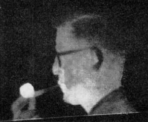
Fig. 1 - Infrared photo (thermograph) taken in total darkness. In this view black areas are at a temperature of 75 degrees F or colder, and white areas are at 133 degrees or hotter. Note that the pipe bowl is the hottest object in the photograph.
Fig. 2 - Black body radiation curves at various temperatures. Note the shift of the peak of maximum radiation that occurs.
Fig 3 - High-resolution infrared tracker installed at Patrick Air Force Base. Photo shows extreme compactness of infrared system compared to antenna of tracking radar on which it is mounted and with which it moves. See text for details.
Fig. 4 - Diagram of the known electromagnetic spectrum showing the near intermediate or middle, and tar infrared bands located between visible light and microwaves.
Fig. 5 - The atmosphere does not transmit infrared uniformly at all wavelengths.
Fig. 6 - Construction of typical thermistor bolometer detector. The "active" flake is mounted so that it can be exposed to radiation, while the "compensating" flake is shielded from radiation and is used to keep arrangement balanced.
Fig. 7 - Circuit of the thermistor bolometer bridge, showing preamp coupling.
Fig. 8 - Hand-held radiometer is employed to measure radiation from intercontinental ballistic missile reentering atmosphere.
Fig. 9 - Curves illustrate the relative sensitivities of various infrared detectors in common usage.
Fug. 10 - Measuring moon's temperature along with chart of actual recording.
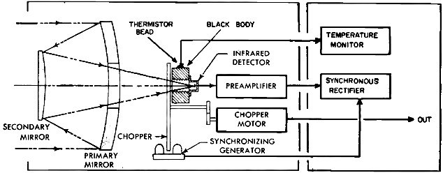
Fig. 11 - The block diagram shown below is that of a basic radiometer system. Tracking is an extremely important application of infrared, which takes over from radar at close range to provide very high resolution results. The U. S. Navy "Sidewinder" is an example of an infrared-guided air-to-air missile which can detect an enemy aircraft at a distance of seven miles, track it down at twice the speed of sound, and make a direct hit. The high-resolution infrared tracker shown on the cover and in Fig. 3 is designed to track high-speed airborne targets in daylight or in complete darkness. Infrared provides much better definition than radar. The resolving power of a radar antenna or infrared optical system increases as its diameter is made larger. Since useful infrared wavelengths are on the order of 1000 times shorter than those of the latest radars, infrared systems provide detail that is unobtainable with radar. For example, a microwave radar operating at 8 millimeter wavelength and with an antenna 12 inches in diameter cannot identify targets at 5-mile range as being separate unless they are laterally separated by more than ¼ mile. On the other hand an infrared system with a 4-inch mirror can easily identify the individual engines on a plane at the same range. There are also many industrial uses of infrared. Infrared radiometers can monitor and control the temperatures of plastics, elastomers, ceramics, textiles, paper, glass, and metals, in all physical states and forms; and measure the temperature distributions of moving and rotating objects. Other infrared applications include non-destructive testing, machine maintenance, and air- craft and missile testing. An interesting new application is the use of infra- red to detect "hot boxes" on railroad freight cars moving at speeds up to 80 miles an hour and to signal ahead to the next station the presence of hot boxes which may cause stoppage or derailment. Such hot box detectors can save many thousands of hours annually by eliminating the need to stop trains for manual inspection. Infrared has many vitally important uses in industrial and scientific laboratories. For example, the infrared spectrometer is used to analyze chemical substances and identify unknown material. Infrared thermographs showing temperature distributions over the human body are being used in cancer research. Agriculture experts are using infrared to investigate temperature differences over supposedly uniform areas of plant life. Meteorologists are using infrared devices to measure the temperatures of sky, air, earth, and sea water; the results promise to be of great value in long-range weather prediction. Infrared Radiation Radiant energy is energy which is propagated through space, at the speed of light, by transfer of electromagnetic vibrations. There is a continuous spectrum of possible frequencies of these vibrations. Gamma rays, x-rays, ultraviolet, light, infrared, microwaves, and radio waves are all forms of radiant energy, and their location in the electromagnetic spectrum can be determined only by their frequencies. They all exhibit wave properties. High-frequency radiation is of short wavelength and low-frequency radiation is of long wavelength. (Refer to chart at bottom of the previous page.) The infrared portion of the spectrum covers the wavelengths from about 0.75 x 10⁻⁶ meter to about 1000 x 10-6 meter (Fig. 4.). These wavelengths are so short that a smaller unit of length, the micron (equals 10-6 meter), is commonly used. Thus the infrared spectrum covers the range from about 0.75 micron to about 1000 microns. For convenience this band is said to consist of the near infrared (0.75 to 1.2 microns), intermediate infrared (1.2 to 7 microns) and far infrared (7 to 1000 microns) regions. The molecules making up all matter are in a state of constant motion. This motion increases as the object's temperature is raised and decreases as the temperature is lowered. At the lowest temperature possible (-273°C), all molecular motion stops. Since all molecules are made up of electrical charges, the oscillations of these molecules cause the radiation of electromagnetic energy. The intensity, frequency, and wavelength of this electromagnetic energy are controlled by the temperature and size of the source and by an interesting property known as the emissivity of the material. When the electromagnetic energy emitted by a source reaches another body, part may be reflected, part may be transmitted, and part may be absorbed to cause heating. Thus infrared radiation is intimately connected with heat, but cannot itself be called heat waves, because it is fundamentally similar to radio waves and light and can be transmitted through vacuum. Other means of heat transmission, such as conduction and convection, require physical media, such as air, or physical contact between the source and the receiver. The standard used in infrared work is the "black body." The black body is an ideal emitter for which the total radiated energy and the spectral distribution of this energy are known. Since the black body is an ideal, it provides only a theoretical relationship between the temperature and radiation. In order to measure practically the relation between temperature and radiation, we need a practical black body which simulates the desired characteristics. Black-body simulators are usually electrically heated, insulated cavities with small apertures. The black-body simulator and its precision temperature controller comprise a radiation reference source that links measurable temperatures and emitted radiation. The infrared energy radiated by a black body covers a wide range of frequencies and wavelengths. The wavelength at which the maximum or peak radiation occurs is determined by the temperature of the black body as shown in Fig. 2. As the temperature increases, the peak radiation shifts to shorter wavelengths and the total amount of the radiated energy increases. Emissivity is an extremely important property. It is defined as the ratio of the radiation emitted by an object to the radiation that would be emitted by a black body at the same temperature. The emissivity of a black body is 1 and the emissivity of all practical materials is less than 1. This property depends on the material and its finish. Dielectrics and insulators in general have high emissivities and metals and other conductors have low emissivities. Polished surfaces have lower emissivities than matte surfaces. The emissivity of a mirrored silver surface is approximately 0.02 and the emissivity of matte lampblack is about 0.95. Transmission of Infrared All electromagnetic radiation is transmitted in accordance with the inverse-square law. This states that the intensity of the energy radiated by a source varies inversely as the square of the distance from the source. Thus the energy at 2 miles from a source would be 1/4 of the energy which would exist at a distance of 1 mile from the source. These statements hold true only in a vacuum and do not take into account the effect of the atmosphere. The atmosphere modifies the transmission of infrared radiation quite markedly. Over short distances, such as used in measuring radiation in laboratories, atmospheric attenuation is negligible. However, over the greater distances which separate military infrared devices from their targets, the problems of infrared transmission through the atmosphere become rather serious. Atmospheric attenuation is caused by water vapor, carbon dioxide, and other gases present in the air, as well as by particles of dust and other substances. There is less attenuation at increasing altitude and especially with lowered water content. The reason for this is that the atmosphere becomes thinner at higher altitudes; so that at altitudes above about 100,000 feet there is comparatively little attenuation. At still greater altitudes, such as those traversed by satellites, atmospheric attenuation of infrared is almost nonexistent, because the atmosphere itself is almost non-existent. As shown in Fig. 5, the atmosphere does not absorb all infrared wavelengths uniformly. Instead most absorption occurs quite definitely at the wavelengths at which the molecules of water vapor, carbon dioxide, and other atmospheric gases resonate and absorb energy from the infrared radiation which passes through. This highly selective absorption of infrared radiation causes a "window" effect. These windows occur at wavelength regions where absorption by carbon dioxide and water vapor is at a minimum. Depending upon altitude and weather conditions, these windows can be used by employing filters which transmit only at the window wavelengths. The principles described so far are fully exploited in modern infrared equipment that is able to perform near miracles of accurate tracking and detection at close ranges. Such equipment uses both the sciences of optics and electronics to do its job. Now let us probe a little deeper into the details of the type of components and systems needed in this type of equipment and its expanding applications. Optical Systems Most infrared devices use special optical systems along with special detectors. The performance of infrared detectors improves as the detectors are made smaller. Therefore very small detectors are used (on the order of 1 millimeter by 1 millimeter square) and the radiation lost because of this tiny size is recovered by placing the detector at the focal point of an optical collecting system. The field of view, or that portion of space which is seen by the detector, is determined by the area of the detector and by the diameter and focal length of the optical system. Optical systems in infrared are like antennas in microwave receivers. The optical gain of an optical system is equal to the ratio of its effective area to the effective area of the detector. Gains of 20,000 times or more are easily obtained with compact optical systems; such optical gain is completely free of the noise which is characteristic of electronic amplification. Between the source and the detecting device there is not only the atmosphere and one or more optical systems, but infrared-transmitting elements such as windows or domes in airplanes to shield or protect infrared devices from high-speed air currents. When radiation strikes solid materials, some of it may be reflected, some may be absorbed, and some may be transmitted. For example, glasses transmit most of the visible energy which impinges upon them; they reflect less, and absorb still less. The properties of glasses and most other materials are usually quite different at infrared wavelengths than they are at visible wavelengths. Many materials which are transparent in the visible spectrum are opaque to infrared wavelengths; while some substances which are opaque to the visible are trans- parent to infrared wavelengths. Most glass transmits up to 2.0 or 2.5 micron, just beyond the visible spectrum. Quartz transmits out to about 4 microns. Rock salt and potassium bromide, which transmit out to 15 and 40 microns respectively, have been used for many years in instruments such as infrared spectrometers. During and since World War II, new materials have been developed and the long-wavelength properties of older materials have been discovered. These materials include the German-developed KRS-5, arsenic trisulfide, sapphire, magnesium oxide, high-purity germanium and silicon, indium antimonide, and certain new glasses. While many new materials with remarkable infrared properties are yet to come, there is a wide enough variety of existing materials to permit the design of new scientific instruments, industrial devices, and military systems. To eliminate as a factor from optical systems the infrared transmission properties of materials, front-surfaced mirrors are used. Mirrors uniformly reflect wavelengths from ultraviolet out through the far infrared. They are unlike lenses, in this regard, since these do not transmit radiation equally at all wavelengths. A large number of high-performance optical mirror systems are in use in infrared equipment; many of them were developed earlier for astronomical telescopes. Infrared Detectors Infrared detectors are used to obtain information from radiation picked up by infrared gear. Such a detector converts incident radiant energy into another form of energy which can be displayed and/or measured. The outputs most frequently used are electrical signals, which can easily be processed, displayed, and measured. Since two of the major effects of radiation on matter are the thermal effect and the photoelectric effect, the two major groups of radiation detectors are thermal detectors and photodetectors. Thermal detectors respond to heating effects which are usually caused by infrared radiation of longer wavelengths. Thermal detectors are power detectors: their output is proportional to the total energy of the absorbed radiation. These detectors are usually blackened to increase the absorption of incident radiation and to reduce reflection and transmission. Thermal detectors make use of the thermal effects of radiation in several ways. Thermocouples and thermopiles employ the effect whereby voltages are generated when junctions of dissimilar metals are heated. Pneumatic cells employ the expansion of gases heated by radiation to move diaphragms. Bolometers employ the changes in resistance of solids when heated or cooled. An extremely important group of thermal detectors are thermistor bolometers. Thermistors are heat sensitive resistors which exhibit large changes of resistance with temperature. When used as radiation detectors, they are made in small and very thin flakes and are solidly backed by heat sinks of high thermal conductivity for fast response to changes in radiation. A thermistor bolometer is constructed by using a closely matched pair of such flakes in an arrangement like that shown in Fig. 6. The detector assembly is quite rugged and resistant to the vibration, shock, temperature variations, high humidity, and other extreme environmental conditions found in industrial and military applications. The bolometer is usually operated in a bridge circuit as shown in Fig. 7, with the two flakes equally and oppositely biased. The output terminal, which is the junction of the two flakes, is thus maintained near ground potential to reduce noise and microphonics. Since the two flakes are closely matched, there is little voltage drift of the output terminal with changes in ambient temperatures. When the bolometer is exposed to radiation, the active flake is heated; its temperature rises, and its resistance decreases. Since the compensating flake is shielded, its resistance is unaffected by the radiation. The output voltage at the junction of the two flakes therefore changes by an amount which is precisely proportional, over a tremendous dynamic range, to the power of the incident radiation. Photodetectors respond to infrared radiation of shorter wavelengths. Fig. 9 shows that while thermal detectors respond almost equally to radiation at all wavelengths, most photodetectors have some long-wavelength limit beyond which their response falls off. Of the various photoelectric effects the one most common for infrared detection is the photoconductive effect. As a result of this effect, the conductivity of certain solid materials changes when radiation is encountered. Photoelectric effects are usually considerably greater than thermal effects, so that special precautions are not usually taken to reduce temperature effects in most photodetectors. The usual circuit for photoconductive detectors is similar to that for the thermistor bolometer detector, except that instead of a compensating element a fixed dropping resistor is used. Some of the most common photoconductive detectors are lead sulfide, lead telluride, lead selenide, indium antimonide, and specially treated germanium. Most photoconductive detectors require cooling to extremely low temperatures for efficient operation. Basic Infrared Radiometer The infrared radiometer can be considered to be the basis of most infrared instrumentation. If the operation of a radiometer is understood, more complex arrangements can be readily followed. Radiometers receive infrared radiation from sources in their fields of view and transform the received energy into electrical signals which can be measured, recorded, and interpreted. Infrared radiometers do not require physical contact with sources being measured; in addition, they have great sensitivity, measuring range, and speed of response. A basic infrared radiometer includes an optical system, chopper, detector, reference source, synchronizing signal generator, and electronics system. A typical arrangement is shown in Fig. 11, while Figs. 8 and 10 show portable radiometers. The optical system is frequently a mirror telescope consisting of concave primary and convex secondary mirrors. Each mirror is aluminized and hard coated. Focusing is usually accomplished by moving the secondary mirror along the optical axis. An infrared detector is located at the focal point of the optical system. Thermistor bolometer detectors are most frequently used because of their very uniform response. A black-body radiation reference source is used as a standard against which target radiation is continuously compared. In the most basic arrangement, the detector is mounted behind a thick metal block and receives incoming radiation through a cylindrical aperture in that block. The aperture has serrated and blackened walls so that it forms a black -body cavity when closed by a reflecting surface. The cavity wall temperature is accurately monitored by a thermistor bead. A mirror-surfaced sector-disc shutter, or optical chopper, is driven by a motor and rotates in front of the black-body aperture. As the aperture is opened and closed by the chopper blades, the detector alternately senses target radiation and black-body radiation. Detector output is an alternating signal, the peak-to-peak voltage of which is precisely proportional to the difference between target radiation and the known radiation from the blackbody. The synchronizing signal generator develops a square-wave signal which drives a phase-sensitive rectifier in the electronics system. As the blades of the optical chopper rotate, they interrupt the light beam between a small bulb and a phototransistor, which generates a square-wave signal of exactly the same frequency as the detector output signal. The synchronizing signal generator can be moved so as to adjust the phase of its output. A preamplifier located close to the detector amplifies the detector output signal to an amplitude and impedance level suitable for transmission through a cable to a remote signal-processing system. The simple signal-processing system shown uses an electromechanical synchronous rectifier. This is a magnetically actuated single -pole, double-throw switch driven by the synchronizing signal and functioning as a keyed full-wave rectifier. It demodulates the preamplifier output, producing a d.c.-output signal exactly proportional to the difference between the radiation from the target and the known radiation from the reference black body. The polarity of the output signal indicates whether the target is hotter or colder than the reference source. Variations in the output signal are precisely proportional to variations in target radiation; so that the d.c. signal can be connected to a voltmeter, calibrated recorder, or control system for continuous radiation or temperature monitoring or control. Other circuits and devices can be added to the basic radiometer. Thus the arrangement can be developed to a form suitable for making thermal photographs, making spectral analyses of materials, tracking a plane or missile, or directing a missile towards a target. All-in-all, this remarkable branch of science which combines electronics and optics promises even more useful and fascinating applications in the future. |
|||||||||||||
 |
|||||||||||||
|
|||||||||||||


|
||||||||||||||||||||||||||||||||||||


