|
"The year 1950 will
be recorded historically as the year the microwave relay made its impact felt."
That was the closing sentence by Philco Sales Engineer Leo Sands in his 1950
Radio & Television News magazine article titled, "The Microwave Era
Begins." Mr. Sands was not suggesting that it was the start of the widespread
use of microwaves in general, but specifically the use of microwaves for long
distance, broadband transmission of telecommunications signals. 1950 is about
the time microwave relay stations began appearing on hilltops and rooftops of
tall buildings all across the land, with the goal of replacing coaxial lines
which needed to be strung or buried from end to end. Great cost is associated
with a hardline approach for acquisition of land rights, installation, and
maintenance. Yes, those kinds of expenses are required for microwave relay
stations, too, but in the long run they tend to be much lower, and the service
much more reliable and "upgradable." Lots of people opposed the installation of
the unsightly, behemoth towers, and many people expressed concern over exposure
to microwave energy. If only they knew then how miniscule their worries were compared
to today's situation with cell towers within eyeshot of just about ever
locations on earth!
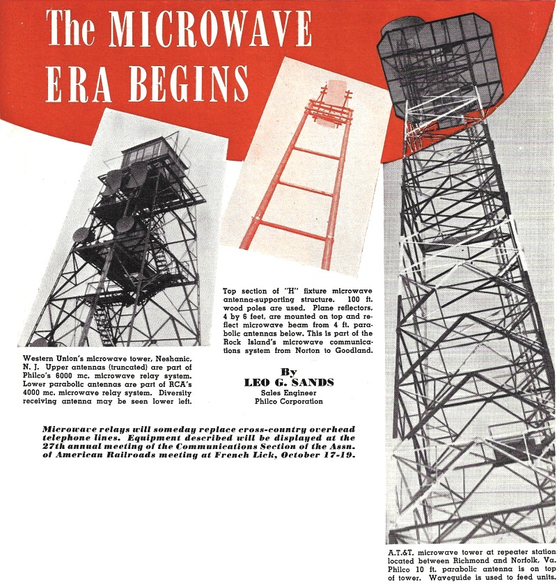
The Microwave Era Begins

Western Union's microwave tower, Neshanic, N. J. Upper antennas
(truncated) are part of Philco's 6000 mc. microwave relay system. Lower parabolic
antennas are part of RCA's 4000 mc. microwave relay system. Diversity receiving
antenna may be seen lower left.
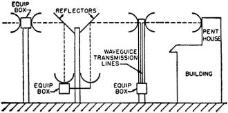
Top section of "H" fixture microwave antenna-supporting structure.
100 ft. wood poles are used. Plane reflectors, 4 by 6 feet, are mounted on top and
reflect microwave beam from 4 ft. parabolic antennas below. This is part of the
Rock Island's microwave communications system from Norton to Goodland.
A.T.&T. microwave tower at repeater station located between
Richmond and Norfolk, Va. Philco 10 ft. parabolic antenna is on top of tower. Waveguide
is used to feed units.
By Leo G. Sands
Sales Engineer Philco Corporation
Microwave relays will someday replace cross-country overhead telephone lines.
Equipment described will be displayed at the 27th annual meeting of the Communications
Section of the Assn. of American Railroads meeting at French Lick, October 17-19.
All over the country, towers topped by queer looking mirror-like reflectors or
parabolic antennas are arising. These towers, spaced from 15 to 50 miles apart,
are spelling the doom of the overhead telephone wires that follow almost every highway
and railroad track. The complete elimination of the pole line is still far off,
but construction of new open wire pole lines, except for local distribution, seems
unlikely.
For several years, there has been talk of the day when beamed radio would start
taking the place of wires for point-to-point overland communications. That day has
arrived. Although the microwave art is not new, inexpensive equipment was not available
until 1949 and very few systems had been ordered prior to 1950.
In the prewar year 1940, a radio relay system was installed by Philco engineers
to bring television programs to New York and Philadelphia. This relay link operated
in the vicinity of 200 megacycles. In 1947 this pioneer radio relay was replaced
with a 1400 megacycle microwave system. During the war, the armed services made
considerable use of microwave and u.h.f. equipment for point-to-point communications.
Today, television broadcasters make use of microwave links to transmit television
signals from their studios to the television transmitters.
Although it is comparatively easy to build microwave transmitters and receivers,
the biggest problem was the design of repeater equipment for long haul relay systems.
A long microwave relay system consists of two terminals and a large number of intermediate
repeaters. These repeaters must be capable of receiving and re-transmitting microwave
signals with a minimum of distortion to provide high quality circuits and very little
crosstalk.
The ideal repeater would consist of a microwave amplifier in which de-modulation
and re-modulation does not take place. However, such a repeater has not yet been
developed. Currently available repeaters fall into three classifications: (1) a
transmitter and receiver connected back-to-back; (2) a heterodyne repeater; and
(3) a feedback repeater. All three types have merit and can be used with multiplexing
systems compatible with the specific type of repeater.
The first commercial application of negative feedback at microwave frequencies
is incorporated in the feedback type microwave repeater developed by Philco. In
this repeater, the output of the receiver is fed back to the receiver's own local
oscillator klystron, causing it to track the incoming frequency modulated signal.
The output of the klystron is divided so that a small percentage of this output
is injected into the mixer of the superheterodyne type receiver and the major portion
of the output is fed into the antenna system as the outgoing signal. To provide
duplex operation, two repeater units, one for each direction of transmission, are
multiplexed into common antennas. Only a single klystron-type tube is required for
both transmission and reception in a single direction.
A back-to-back type of microwave repeater consists of a receiver whose output
is fed to a transmitter. For duplex operation, two transmitters and two receivers
are required at each repeater station. In this type of repeater at least two microwave
oscillator tubes are usually required for each direction, one as the receiver local
oscillator and the other in the transmitter.
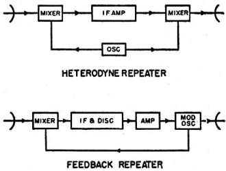
Block diagram show simplified circuitry of two types of microwave
repeater units.

A four-section r.f. filter for a Philco microwave receiver. This
is part of the Philco CLR-5 repeater for use in 6575-6875 mc. band. Tuning slugs
are pretuned and sealed at factory.
The heterodyne type repeater is not commonly used in communications relay systems
due to its cost and complexity. However, it has found wide use in television relays.
Here a comparatively low frequency signal produced by beating the incoming modulated
microwave signal with the output of the receiver local oscillator is amplified.
This low frequency signal (v.h.f.) is used to beat against a microwave oscillator
to produce a microwave signal at the sum or difference of the two frequencies.
Several types of tubes are used as microwave signal sources and include lighthouse
tubes, planer triodes, magnetrons, and klystrons. Power outputs of these tubes vary
from a few milliwatts to several watts.
Several groups of radio frequencies in the microwave region have been allocated
by the Federal Communications Commission for point-to-point use by various industries,
transportation services, public safety organizations, broadcasters, and communications
common carriers. The 6000 megacycle band offers many advantages, such as high antenna
gain, adaptability to simple circuitry, availability of reliable long-life tubes,
and excellent propagation characteristics.
Antennas with parabolic reflectors are generally employed. The effective power
gain, for example, of such an antenna with a dish of four foot diameter is in the
order of 34 db. at 6500 megacycles. This means that a one watt transmitter will
effectively radiate the equivalent of a 2500 watt signal. A waveguide is often used
for connecting the antenna to the microwave transmitter, receiver, or repeater.
Alternatively, passive reflectors are used in lieu of long waveguide runs. A plane
reflector, rectangular in shape, is mounted atop a tower or other suitable supporting
structure and the parabolic antenna is mounted near the ground aimed at the reflector.
The signal is bounced off the mirror-like reflector in the desired direction in
the same manner as a beam of light is reflected by a mirror. In practice the parabolic
antenna dishes are usually mounted on brackets on the roof of the equipment shelter.
As the antennas are exposed to the elements, heating facilities are provided for
feed horns and antenna dishes when used in cold climates. With the antennas mounted
outdoors, there is the possibility that the dishes may be eventually filled with
leaves, dirt, or snow. Furthermore, the end of the feed horn makes an attractive
target for the hunter. To provide greater protection for the paraboloids and feed
horns, Philco engineers have recently designed a new type of microwave equipment
shelter in which the antennas are mounted indoors under the roof. Windows made of
a special type of pressed Fiberglas, virtually transparent to microwaves but opaque
to light, are installed in the slanting roof of the shelter. The antennas are aimed
through these windows at the plane reflectors on the tower. To prevent frosting
or the accumulation of snow, thermostatically controlled infrared lamps are used
to heat the Fiberglas windows.
One antenna with or without a plane reflector is used at terminals for simultaneous
transmission and reception. Two antennas are required at repeater stations in combination
with waveguide feeds or plane reflectors, each of which is used for transmitting
and receiving simultaneously in one direction to and from the adjacent repeater
or terminal.
The popular term for a single link, the space between adjacent repeaters or terminals
is a "hop." For example, a three hop system consists of two terminals and two repeaters.
The signal originating at a terminal on frequency f1 is retransmitted
by the first repeater on frequency f2 and is retransmitted again on frequency
f1 by the second repeater. The signal arrives at the far terminal in
three hops. For duplex operation, another signal travels simultaneously in the reverse
direction.

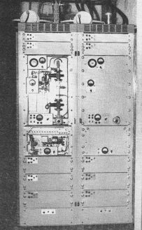
Philco CLR-5 microwave repeater for 6575-6875 mc. band. Two complete
one-way feedback repeaters and common power supply are housed in a single cabinet.
The microwave carrier is frequency modulated. It may be used with frequency-division
or time-division multiplex terminals. Only one klystron is required for each direction.
The same klystron serves both as the receiver local oscillator and the FM transmitter
tube.
Philco TLR-2 microwave repeater for television service as used
by Western Union. A similar unit is used by American Telephone & Telegraph Company
in its microwave relay system.
The practical length of a hop is determined by the heights of the antenna supports,
terrain, transmitter power, receiver sensitivity, and antenna gain, coupled with
good engineering practice. Line-of-sight conditions are not good enough except for
very short hops. At least 50 feet of clearance above trees is considered desirable.
Hops varying in length from 15 to 50 miles are common. Longer hops where sufficient
terrain clearance is available could be considered, however, long hops are more
apt to suffer from fading.
A properly designed microwave re-lay system makes allowances for fading. When
frequency modulation of the microwave signal is employed, shallow fades go unnoticed.
A microwave system with a 30 db. fading margin provides a continuous signal without
serious degradation of circuit quality even during deep fades. In the 2000 megacycle
band, deep fades are not as frequent as in the 6000 megacycle band. However, the
higher antenna gain available at 6000 megacycles permits designing a system with
a greater fading margin, with the result that operation in either band is almost
identical. The hop length at 2000 megacycles or 6000 megacycles can be the same,
as here again the much greater antenna gain at the higher frequency more than compensates
for the slight difference in propagation characteristics.
The width of the transmit-fed beam from a four foot parabolic antenna at 6000
megacycles is three degrees. Although this appears to be a very narrow beam, 25
miles out it is over a mile wide at the half power points. Much emphasis has been
placed on tower twist, but an analysis of the facts reveals that tower rigidity
is not as important as has been popularly supposed. As fading seldom occurs at the
same time as high wind velocity, the fading margin also compensates for tower twist.
The basic microwave system is capable of a modulated intelligence bandwidth of
considerable proportions. To transmit several simultaneous voice conversations,
musical programs, telegraph messages, etc., the modulation acceptance band of the
microwave system is subdivided by means of multiplex channelizing equipment. These
fall into two general classifications, frequency-division and time-division multiplex
systems.
The most common form of frequency-division multiplexing device is the standard
telephone wire line carrier terminal employing AM with single sideband transmission
and with the carrier suppressed. This type of channelizing equipment which is very
economical with bands pace may be used with single hop systems or with multiple
hop microwave relay systems employing repeaters which introduce very little distortion.
As the carrier is suppressed, this type of multiplex equipment lends itself to party-line
service on a bridging basis. Telephone carrier terminals of the single side-band
type but without suppression of the carrier may be used for deriving through circuits
but not bridged party-line channels.
Another form of frequency-division multiplex system is the FM subcarrier which
lends itself well to microwave applications where economy of band-space is not important.
The FM subcarrier is not as critical of repeater distortion as is the single sideband
suppressed carrier, hence it may be effectively used with the back-to-back type
of repeater. However, its extravagant use of bandspace does limit the number of
channels that can be derived.
Several types of time-division multiplexing systems have been developed, making
use of pulse amplitude modulation, pulse time modulation, pulse position modulation,
pulse width modulation and pulse code modulation. Pulse amplitude modulation, popularly
referred to as P.A.M. provides high quality voice circuits with a minimum of crosstalk
and with economical use of bandspace. For example, a 32 voice channel P.A.M. multiplex
terminal requires less than 300 kilocycles of bandspace. With P.A.M. it is possible
to provide party-line circuits as well as through trunk circuits. Individual voice
channels may be dropped off and injected at intermediate microwave repeaters without
degradation of the channel.
A cost analysis reveals that for systems requiring four or fewer channels, particularly
when many drop-off's are required, frequency-division multiplexing is less expensive,
whereas in systems with a greater number of voice channels, time-division multiplexing
can be provided at less cost. Unless otherwise specified a channel is a voice channel
300 to 3300 cycles wide. Telegraph, teleprinter, telemeter, and supervisory control
channels require much less bandspace than a voice channel. When a frequency-division
multiplexing system is used for deriving voice channels, narrow-band carriers for
on-off transmission, such as telegraph carriers, are generally applied directly
to the microwave equipment modulation input. In time-division systems, a single
voice band may be subdivided to handle from 8 to 16 AM or frequency-shift telegraph
or telemeter carriers.
How microwave signals are relayed.

Block diagram of carrier amplifier repeater and back-to-back
receiver-transmitter.
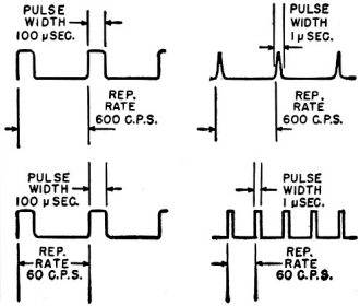
Fig. 4 - Oscilloscope patterns obtained.
With the exception of communications common carriers, the channel requirements
of most potential users of microwave communications systems does not approach 32
voice channels. Manufacturers are offering multiplex systems with 3, 4, 5, 8, 10,
12, 16, 20, 24, or 32 voice channels as required by the user. Some of the equipment
being offered is expandable in steps of 1 or 4 voice channels.
To provide compatibility with telephone systems the multiplex terminals must
be provided with suitable termination equipment. A two-way voice channel normally
terminates on a four-wire basis, two to the transmitter input and two from the receiver
output, so that a hybrid network is required to provide two-wire termination which
will permit connection into a switchboard or a conventional telephone instrument.
In addition, provision must be made for ringdown or dial signaling.
Although the microwave industry is just starting to grow, great progress has
already been made in the past year. The first railroad-operated microwave communications
system to be established on a permanent basis has been installed by the Chicago,
Rock Island and Pacific Railroad along its Denver to Chicago main line. This 5 hop
pilot system between Norton and Goodland, Kansas will supplement and perhaps eventually
replace wire line communications facilities in an area where snow, wind, sleet,
and dust raise havoc with pole lines. Initially, the Rock Island's 6000 megacycle
microwave link, 106 miles in length, will provide facilities for a train dispatcher's
party-line telephone channel, a party-line message telephone channel, a local party-line
telegraph circuit, and four through telegraph circuits.

Lower section of "H" fixture antenna support and microwave equipment
shelter. This Philco Type CLR-5 microwave repeater and emergency gasoline engine-driven
power generator are housed within the prefabricated concrete slab building. A pair
of 4 ft. parabolic antennas are mounted on the- roof.

Four foot parabolic antenna for the 6575-6875 mc. band. The unit
has a three degree beam and an effective power gain of 34 db.
The Santa Fe Railway System is installing a 6000 megacycle microwave communications
system to provide additional communications facilities between Beaumont and Galveston,
Texas. Eight voice channels derived by pulse amplitude modulation will be provided.
Three unattended repeater stations are to be installed on the Bolivar Peninsula
to make up a four hop relay system. To assure uninterrupted communication, standby
microwave equipment will be provided at both terminals as well as at the repeaters.
An automatic fault-alarm system will advise maintenance personnel at Galveston of
equipment or primary power failures as well as identification of the station requiring
attention.
In the petroleum industry, a number of pipe line companies are installing microwave
relay systems to provide direct communication between pumping stations, regional
offices, and for remote control of system-wide v.h.f. mobile radio systems. The
Humble Pipe Line Company is to install a 6000 megacycle microwave communications
system along 400 miles of pipe line between Houston and Kemper, Texas. Two terminals
and eighteen intermediate repeater stations will make up the Humble relay system.
Pulse amplitude modulated multiplex equipment will provide eight voice channels
of which one to four will be dropped off at intermediate repeaters.
The Bonneville Power Administration of the United States Department of the Interior
has awarded contracts for equipment for a vast microwave relay system which will
blanket the State of Washington. In circuit miles, this will be the largest microwave
system ordered to date for non-common carrier service. The Bonneville communications
network will also make use of pulse amplitude modulation for deriving up to 24 voice
channels. In addition to telephone facilities, the microwave system will also be
used for power line relaying, remote control, and the locating of faults along power
transmission lines.
For relaying of television programs, a number of microwave relay systems have
already been installed and many more are projected. A 6000 megacycle microwave link
installed by the Western Union Telegraph Company has been in continuous operation
for over two years. This link extends from the Chrysler Building in New York to
the P.S.F.S: Building in Philadelphia via two intermediate repeaters located at
Neshanic and Mt. Laurel, N. J. Paralleling this link is the Philco-owned television
relay which links the Empire State Building in New York with the WPTZ transmitter
at Philadelphia. One intermediate repeater at Mt. Rose, N. J., joins the two terminals.
The American Telephone & Telegraph Company has a number of microwave relay
systems in operation and according to the newspapers many more are planned. In April
of 1950, a 6000 megacycle microwave relay system was placed in service between Richmond
and Norfolk, Virginia, by the Bell System to feed network TV programs to the Hampton
Roads area.
It is obvious that the microwave relay art has emerged from the experimental
stage to become a vital part of the nation's communications system. In times of
national emergency, microwave relay systems can be used to augment existing wire
line facilities and they can be installed in much less time. Economically, wire
lines cannot compete, as the cost of a microwave communications system runs from
only $400 to $800 per mile. The current estimated cost of building a two-wire pole
line runs from $800 to $1500 per mile. A pair of wires will provide one telephone
circuit unless multiplexed. The number of channels that can be derived from a single
pair of wires is limited by electrical losses. Multi-channel carrier equipment for
wire line telephony is more expensive and more complex than microwave multiplex
equipment.
Performance-wise, the microwave relay, being less vulnerable to storms, should
provide greater reliability than overhead wire lines. Furthermore, it will carry
more types of intelligence and can be expanded more readily and at lower cost. Microwave
systems have provided uninterrupted service during snow, sleet, and wind storms
which have prostrated wire lines. With well designed equipment and adequate preventive
maintenance, reliability approaching 100% can be attained.
The year 1950 will be recorded historically as the year the microwave relay made
its impact felt.
Posted April 7, 2022
|